asavage
Member
What would be a bonus, is if we could get a baseline rotor temp (using the same or similar setup) before modding for coolant delete.Looking forward to ur data from driving.


You can install our site as a web app on your iOS device by utilizing the Add to Home Screen feature in Safari. Please see this thread for more details on this.
Note: This feature may not be available in some browsers.
What would be a bonus, is if we could get a baseline rotor temp (using the same or similar setup) before modding for coolant delete.Looking forward to ur data from driving.


Many thanks Howard for the thought collaboration and loaning your leaky LDU for the measurements, test fitment and first install of this piece! While I respect the more complete solution of a complete replacement manifold, I'm a DIYer at heart and saw the need for this after wondering if I'd be willing to drill/sleeve/weld my own manifold to do a DIY bypass. This solution will allow anyone with basic DIY skills and tools (Dremel and bench vise) to do a coolant delete. The most challenging part of the job will obviously remain the removal/install of the LDU from the car. There isn't an easy way around that!
The production run of these caps will be arriving in a few weeks. I don't want to handle retail sales of individual units from my home so I'm hoping to find someone with a presence in the community and an existing digital storefront to handle that. I'll wholesale to shops/professionals in larger quantities.
")
a bit pricey but great to see yet another alternative n 2 piece design...Additionally, for those in Portugal, I stumbled upon a coolant delete kit available at:
Tesla LDU SEAL DELETE kits | speev
Thank you in advance for any assistance provided.
Before you waste too much time and money on parts, be sure to disassemble the unit and check the resistance of each winding of the stator. If it has an internal short you need a completely new drive unit. I have three with dead shorts in the stator windings.Hello everyone,
I find myself in a similar situation where I received a message on my display (2014 MS P85, got the “P” version LDU in 2017) regarding a potential coolant leakage issue that may prevent my car from starting. Before I embark on the repair process (rotor coolant delete), I'm ensuring I have all the necessary parts. According to the service manual and common practice, it's essential to replace certain o-rings and seals. Does anyone have a comprehensive list of sizes for these components? While I know Tesla provides these (not all, jsut most of the) parts, I'm uncertain about their prices and would prefer to explore local shops for alternatives. (2 pcs Axle seal, HV cables,Pipes,Coolant line o-rings, etc)
Around the bearings there is a special red o-ring size is unknown?! What is the purpose using o ring on the bearing house? (I saw that cad youtube video from DIY EV Guy)
In my town there is a Toyota official service but Tesla is far away.
I've managed to locate the sizes for the bearings online (btw this community is amazing!). As I'm based in the EU, I'm opting for SKF hybrid bearings. Oil will be Dexron VI, 1.4 litres.
Silicone will be CX-80 or Permatex Ultra Black.
Additionally, for those in Portugal, I stumbled upon a coolant delete kit available at:
Tesla LDU SEAL DELETE kits | speev
Thank you in advance for any assistance provided.
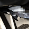
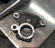
nice, thanks for feedback n picsGood thread with lots of information and options! Took the easy way out and eliminated cooling to the rotor and diff by cutting off the original cooling manifold and just gave full flow to the stator. I removed the coolant tube and capped off either end. Been running it for a few weeks and everything seems great, possibly slightly lower stator temperatures.

I have a performance ldu in a '72 Plymouth. Yep, the 3D printed caps work perfectly.nice, thanks for feedback n pics
were u able to get to both tube ends easy?
what car u have, performance or regular?
cool kit but lol at 3d printed caps
IDK about in the Model S, but the LDU in the RAV4 EV has access to the three HV stator bolts without dropping the LDU. IOW, the orange plastic cap can be removed and an insulation resistance tester (applies 500V to the stator windings; this is not a function of a standard DMM -- I have a Fluke 1507) can be used to check stator isolation resistance without removing the LDU.Before you waste too much time and money on parts, be sure to disassemble the unit and check the resistance of each winding of the stator. If it has an internal short you need a completely new drive unit. I have three with dead shorts in the stator windings.
Aren't u suppose to disconnect those first?IDK about in the Model S, but the LDU in the RAV4 EV has access to the three HV stator bolts without dropping the LDU. IOW, the orange plastic cap can be removed and an insulation resistance tester (applies 500V to the stator windings; this is not a function of a standard DMM -- I have a Fluke 1507) can be used to check stator isolation resistance without removing the LDU.
Not bad for the inverter and won't narrow down the issue to the stator but will identify the potential for a stator failure.Aren't u suppose to disconnect those first?
Otherwise you'll be sending 500v thru inverter as well...
Could be bad for inverter or at least skew the result...
good to knowThe inverter IGBTs' outputs can more than handle 500v, NP. I disconnected mine when I had my LDU on the bench two weeks ago, because I did want to eliminate the variable of the IGBTs in measuring my stator's isolation resistance, but in practice the readings connected/disconnected were nearly identical; the time slope varied, but other than that I'd say that disconnecting is not needed.
If I was performing this test on an installed LDU, and I received low readings, I'd be disconnecting the HV leads from the rear HVJB to the inverter next . . . but in theory there is no connection between the stator and the rest of the vehicle except through the IGBTs, and if one of those has a low junction resistance, then other problems would very likely have surfaced pretty fast.
Good thread with lots of information and options! Took the easy way out and eliminated cooling to the rotor and diff by cutting off the original cooling manifold and just gave full flow to the stator. I removed the coolant tube and capped off either end. Been running it for a few weeks and everything seems great, possibly slightly lower stator temperatures.
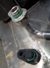
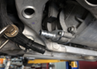
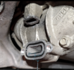
Nice implementation of the LDU non removal fix! I would suggest 3d print a connector that connects the pipe that goes to the heat exchanger to the main coolant line instead of capping it.So I did the coolant delete today. I cut the manifold with a reciprocating saw and capped the bottom part and upper part with JBweld water weld. I used a 3/4 1/2 3/4 tee to supply coolant to the upper tube that goes to the heat exchange. It took me about an hour. I had to top off the reservoir with about a gallon of coolant every now and then. Drove for 10 min so far so good.
Good job on the delete! I thought about routing coolant back to the tube, but I cannot come up with any benefit to bleeding off some coolant to the top of the diff heat exchanger. I think I prefer increased flow through the stator, and keeping it simple.Nice implementation of the LDU non removal fix! I would suggest 3d print a connector that connects the pipe that goes to the heat exchanger to the main coolant line instead of capping it.