Welcome to Tesla Motors Club
Discuss Tesla's Model S, Model 3, Model X, Model Y, Cybertruck, Roadster and More.
Register

Questions regarding backup lugs in gateway

This site may earn commission on affiliate links.
Here is my wirings for the house:

Grid ---> Main panel (w/ some loads) ---> Gateway (w/ PW+Solar) ---(backup lugs)---> backup panel
|___________(non-backup lugs)---> AC/Heater

My understanding is that (please correct me):
1. During outage, my backup panel will be powered by PW, but AC/Heaters and loads in main panel will lose power. This is what I desired.
2. When grid is still on, and it is peak price hour, PW will also power AC/Heater though they are on non-backup lugs. Is this correct? Assuming power usage is within PW capacity.

I searched and read past posts and would like to get some confirmation if my understanding is correct:
3. If I add a CT between grid and main panel and connect to Gateway, GW would know my overall usage and can feed back to main panels duing peak hours (Grid is on)? This would be the most ideal situation as I can completely skip the non-backup lugs wirings and keep AC/Heater in the main panel.
 
1. During outage, my backup panel will be powered by PW, but AC/Heaters and loads in main panel will lose power. This is what I desired.
Correct.
2. When grid is still on, and it is peak price hour, PW will also power AC/Heater though they are on non-backup lugs. Is this correct? Assuming power usage is within PW capacity.
Correct, as long as the CTs are setup properly to monitor the extra non-backup loads. This is very common and how my home is setup.

Refer to Figure 3:
3. If I add a CT between grid and main panel and connect to Gateway, GW would know my overall usage and can feed back to main panels duing peak hours (Grid is on)? This would be the most ideal situation as I can completely skip the non-backup lugs wirings and keep AC/Heater in the main panel.
I have many non-backup circuits way beyond the gateway and they are properly fed by the Powerwalls when the grid is on.

Context: I have 400A service to a split 200A / 200A meter. The powerwall is responsible for an entire 200A leg and the other leg is for non-backup loads.

When the grid is up, I can charge my EV (non-backup load), bake a Turkey (non-backup load) and the Powerwalls could power them. Even though they live outside the Tesla Gateway. Because the Gateway has CT(s) tracking the other 200A leg to the house. So, the non-backup loads are still within its “jurisdiction”.

When the grid is down, the non-backup loads on the non-backup leg are outside of the Tesla Gateway and have no power. The Gateway isolates itself from the grid and only powers backed-up loads on its 200A leg.
 
Correct the wiring graph, spaces are auto-deleted in OP:

Grid ---> Main panel (w/ some loads) ---> Gateway (w/ PW+Solar) ---(backup lugs)---> backup panel
.................................................................................. |___________(non-backup lugs)---> AC/Heater

The non-backup leg is the one inside the gateway.
 
I have many non-backup circuits way beyond the gateway and they are properly fed by the Powerwalls when the grid is on.

Context: I have 400A service to a split 200A / 200A meter. The powerwall is responsible for an entire 200A leg and the other leg is for non-backup loads.

When the grid is up, I can charge my EV (non-backup load), bake a Turkey (non-backup load) and the Powerwalls could power them. Even though they live outside the Tesla Gateway. Because the Gateway has CT(s) tracking the other 200A leg to the house. So, the non-backup loads are still within its “jurisdiction”.

When the grid is down, the non-backup loads on the non-backup leg are outside of the Tesla Gateway and have no power. The Gateway isolates itself from the grid and only powers backed-up loads on its 200A leg.
Thanks, that helps, so I don't need to move AC/heaters from main panel to non-backup side of the GW, that's a much simpler wiring.

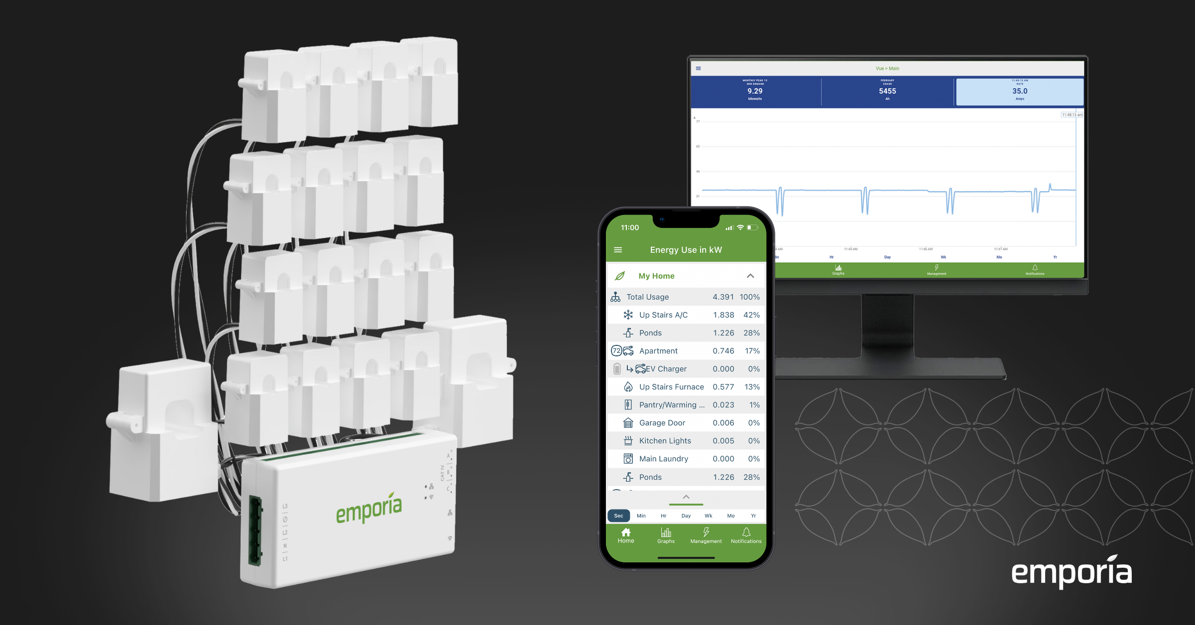
The only challenge I have it is the CT. The grid and main panel is a bus bar connection and little space left to add a regular size CT. I am looking for something like Emporia one:

Any suggestions you have? My meter is 200A, I guess I need 200A:66ma ratio but with a flexible sensor.
 
One key thing that should be pointed out in this thread is that the Gateway 2 has built-in CTs to measure the grid input to the Gateway. The Non-Backup lugs in the Gateway are fed power that has already been measured at the Grid input. If the system is trying to offset all grid usage, solar and/or Powerwall energy will flow to the Non-Backup loads instead of grid power.

If you have any loads between the Grid input of the Gateway and the meter, then you need additional CTs and possibly a remote Neurio device in order for the Powerwall system to "see" those loads. These additional CTs should be placed between the loads and the meter. The grid feed to the Gateway can be included, or not, but the configuration settings have to account for that. If the new CTs measure ALL grid flow, then the CTs built into the Gateway need to be disabled and the new CTs designated as the Grid measurement. Otherwise, like the case mentioned above with two 200A main breakers, the additional CTs can be added to the CTs built into the Gateway in order to get the total grid usage of the home.