Hi everyone,
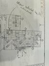
I wanted to get feedback on the layout of our system design, specifically how the solar strings are tied into the inverters. There are 6 separate arrays due to the rooflines and other obstructions that has panels facing all 4 directions.
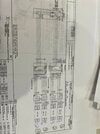
My first observation was that the groupings as tied into the inverters made sense and it looked like they were utilizing as many inputs as possible of the inverters (2x4 available). After more reading and a closer look, it appears there are 3 separate groups that have jumpers (ex MP4 and MP2) vs being separately handled (MP5 and MP6). Any feedback on this specific setup? My hope would be the strings were as independent as possible since some face different directions (MP4 and MP2) or will have some shading effects (MP1).
Another related but different question is does the diagram provide any insight into how the arrays will be tied together coming from the roof? My original assumption was that each MP would have a separate ‘run’ to get to the inverter. This would mean no MPs would be in parallel or series prior to the inverter. I’m not sure that assumption is correct based off of other discussions I’ve seen despite how the diagram shows 8 separate ‘blocks’ coming into the inverter setup. For example MP1 is shown as 2x6 at the inverter but appears to have jumpers. Does that mean MP1 will have 2 sets of wiring running from the array (6 panels each) but then tied together at the inverter?
I appreciate any feedback anyone has and let me know if there are any additions l details needed. I did my best with the photos but let me know if there’s a better way to post them.
Thank you


I wanted to get feedback on the layout of our system design, specifically how the solar strings are tied into the inverters. There are 6 separate arrays due to the rooflines and other obstructions that has panels facing all 4 directions.
My first observation was that the groupings as tied into the inverters made sense and it looked like they were utilizing as many inputs as possible of the inverters (2x4 available). After more reading and a closer look, it appears there are 3 separate groups that have jumpers (ex MP4 and MP2) vs being separately handled (MP5 and MP6). Any feedback on this specific setup? My hope would be the strings were as independent as possible since some face different directions (MP4 and MP2) or will have some shading effects (MP1).
Another related but different question is does the diagram provide any insight into how the arrays will be tied together coming from the roof? My original assumption was that each MP would have a separate ‘run’ to get to the inverter. This would mean no MPs would be in parallel or series prior to the inverter. I’m not sure that assumption is correct based off of other discussions I’ve seen despite how the diagram shows 8 separate ‘blocks’ coming into the inverter setup. For example MP1 is shown as 2x6 at the inverter but appears to have jumpers. Does that mean MP1 will have 2 sets of wiring running from the array (6 panels each) but then tied together at the inverter?
I appreciate any feedback anyone has and let me know if there are any additions l details needed. I did my best with the photos but let me know if there’s a better way to post them.
Thank you