Welcome to Tesla Motors Club
Discuss Tesla's Model S, Model 3, Model X, Model Y, Cybertruck, Roadster and More.
Register

Need wiring advice

This site may earn commission on affiliate links.
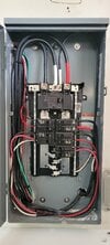
Hey everyone, I had a guy install a 50 amp breaker for an induction stove and another one for a hot tub (the bottom breaker on the left and right sides). This is in my main backup panel which encompasses my whole house. So from this panel is the meter and a single 200 amp breaker and I believe that is where the ground is run.

I wanted to make sure it was wired correctly and now I'm having doubts. I see he wired the neutral and ground to the bus bar. Which seems like that's fine as long as it is the main panel but I don't think it should be here as none of the other breakers even have a neutral or ground here.

Could you help guide me if I need to make a change? If you need more pictures or info please let me know.

Thanks in advance!
 

Attachments

  • 20221223_102322.jpg
    20221223_102322.jpg
    326.6 KB · Views: 206
That picture definitely shows a couple problems. I take it the two black cables coming in the lower right are the two new circuits?

1) The cables need to be secured to the enclosure, e.g. with a clamp.
2) Grounds and neutrals are to be separate other than at the service disconnect, as you noticed.
3) If this is outdoor (it's a weatherproof enclosure) and mounted on the exterior wall, then the wall penetration the cables come through needs to be air sealed and made weather tight.

I notice there's no wire-type grounding conductor (EGC). That can be fine if one of the conduit entries qualifies as an EGC. I'm guessing there's another panel on the backside of the wall, and the lower left conduit entry is just a short nipple between enclosures. If that's correct, and if there are proper conduit terminations with tight locknuts, that could be your EGC. I'm also guessing that the panel behind is the original panel with most of the circuits, and just the two 240V-only circuits were relocated to this panel, by extending their ungrounded conductors through that nipple.

So if my guess is correct (requires confirmation), then the solution to (2) is simply to add a ground bar mounted on the enclosure (with the paint at the mounting point removed to ensure a good bond), and to land the new circuit EGCs on that ground bar. As well as confirming that the panel shown does not have any bonding screw or bonding jumper installed in it (I'm not familiar with what those look like in all cases, but I don't see one).

Cheers, Wayne
 
Last edited:
Hey Wayne,

Thanks for the detailed analysis! So it is actually inside my garage, the panel shown. My true main panel is on the other side of this wall which is exterior. Tesla did the original install of this panel minus the two new loads that are coming in from the bottom right as you noticed.

Would you still recommend a ground bar or do I somehow need to route these neutral and ground wires to the panel on the other side and the ground bar that presumably is in it? (I need to open it up also)
 
So it is actually inside my garage, the panel shown. My true main panel is on the other side of this wall which is exterior.
So to comment further I'd want to see a one-line diagram (should be part of Tesla's permit package, which you are supposed to end up with, but may not have). I'm not clear on what is supplying this panel and what the 100A breaker is supplying. Likewise what enclosure is on the outside of that lower left nipple, and what is coming in at the upper left and just running through the panel?

As to the cable entry, are the cables running inside the wall to come to the panel shown? If so you just need a clamp (as far as the entry issues, not the grounding issue).

Cheers, Wayne
 
Last edited:
  • Like
Reactions: Shygar
Yep those are inside the wall. One runs directly to the plug behind the stove and the hot tub one runs to a separate 50 amp GFCI sub panel. The 100 amp powers my entire house minus stove, hot tub, AC condenser, Tesla wall connector that you see in the first picture.

My backup gateway is what is behind this panel in the original picture. Attached are the pictures of the backup gateway, the main panel from the grid and the diagram from Tesla.

FYI I had the gateway and one Powerwall installed in 2017 with partial backup. Then in Feb this year had Tesla install a second Powerwall and make it whole house backup.
 

Attachments

  • Screenshot_20221223_163852_Acrobat for Samsung.jpg
    Screenshot_20221223_163852_Acrobat for Samsung.jpg
    174.9 KB · Views: 92
  • 20221223_164359.jpg
    20221223_164359.jpg
    400 KB · Views: 69
  • 20221223_164554.jpg
    20221223_164554.jpg
    339.5 KB · Views: 85
Last edited:
OK, I haven't fully sussed out all the connectivity, but it seems clear that the garage panel shown in the OP is supplied from the Gateway load side lugs as expected. Then all you need to have done (besides the clamp for the cables) is to confirm that the nipple between the Gateway and the garage panel in the OP is a proper EGC, then add an EGC bar in the garage panel in the OP, and move the two bare conductors to the EGC bar. Or if you can't confirm about the nipple, run a #6 copper or #4 Al EGC (if the garage panel's main breaker is 200A) from the ground bar at the top of the Gateway, through that nipple, to the new ground bar in the garage panel.

"The guy" should have realized that the above needed doing and shouldn't have landed those bare EGCs on the neutral bar.

Cheers, Wayne
 
Last edited:
  • Like
Reactions: Shygar
Thanks Wayne! Really appreciate your time looking at it. So the neutrals are fine on the existing bar in the 200 amp sub panel in the garage, it's just the grounds that need to be moved off in either of those ways you mentioned (depending on the result of the nipple being grounded). Just wanted to confirm.
 
Thanks Wayne! Really appreciate your time looking at it. So the neutrals are fine on the existing bar in the 200 amp sub panel in the garage, it's just the grounds that need to be moved off in either of those ways you mentioned (depending on the result of the nipple being grounded). Just wanted to confirm.
Yes. Plus confirm that there's no neutral-ground bonding screw/jumper in the garage subpanel. It would be bonding the neutral bars and strap at the top to the case of the panel.

Cheers, Wayne
 
  • Like
Reactions: Shygar
Yes. Plus confirm that there's no neutral-ground bonding screw/jumper in the garage subpanel. It would be bonding the neutral bars and strap at the top to the case of the panel.

Cheers, Wayne
I see a spot where a screw could go so I think it's not bonded to the case. Does that mean my loads weren't actually grounded before? I'm glad I double checked my electrician's work, I will not be using him again.

I just added the grounding bar to the sub panel now and ran it straight to the main panel. Here's a picture of it after finishing:

20221225_142437.jpg

And also of my main panel before I attached the 6 gauge green ground wire to the ground bar:

20221225_134221.jpg

Thanks for all your help Wayne! Happy holidays!
 
I see a spot where a screw could go so I think it's not bonded to the case. Does that mean my loads weren't actually grounded before?
It's good that there's no bonding screw, as that would bond the neutral bus to the case, which is to be done only at the main panel. [But the panel is designed to be useable as a main panel, so it has provisions for a bonding screw.]

The lack of a grounding bar in the subpanel is surprising but fine if the feeder supplying it and the branch circuits it supplied (before you added any) were all run in metallic conduit, as that serves as the EGC. But now that you have some circuits run in a cable method, you need the ground bar to supply the cables' EGCs.

I just added the grounding bar to the sub panel now and ran it straight to the main panel. Here's a picture of it after finishing:
So the #6 to the main panel is unnecessary if the feeder supplying the panel is in a metallic nipple which is serving as the EGC. But it doesn't hurt. It would also be more typical to just run the wire-type EGC to the source of supply of the feeder supplying the panel, which would be the Gateway, but again it doesn't hurt that it went back to the main panel.

Now, to properly do the terminations you made (at the main panel and at the new grounding bar), you are supposed to use a torque screwdriver and follow the torque specs that should be on a label inside each panel. So if you didn't do that, I recommend getting a torque screwdriver.

Cheers, Wayne
 
  • Like
Reactions: Shygar