Thank you everyone, and thank you for the diagram. I’m confused though, if that diagram is for me, what was the reasoning for downgrading it to 100 amps?
My electrical system will be activated before Tesla even comes out. My electrician said he probably wouldn’t be able to feed a 200 amp sub panel from the main 200 amp panel. I don’t know if it’s not possible to take two 100 amp breakers, and interconnect them?
I did speak to Tesla, they said I could get the 6 circuit panel board inside of there. My question here:
1. I have a 200 amp disconnect breaker outside, so I need one on the panel for the entire thing? This would shut power off to both back up and non back up?
2. With the Gateway, if I upgrade the 125 Amp sub panel to a 150 amp sub panel, would there be two separate 200 amp breakers in the sub panel?
Tesla said the generation panel is not used or needed for power wall installations. Thanks!
PS, the rep from Tesla I use, it’s constant emailing. I email to ask a question, and he ignores it or bypasses it. For example, I asked specifically to write out how the power would be routed to help me understand, and he then says the design team won’t do any of that until things are finalized. I didn’t ask about the design team, I asked him...then I email back again telling him he has failed me, and he did not answer my question.
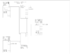
Thankfully some awesome person on here drew a diagram and that answers my question.
Power flow:
1. Meter
2. 200 amp exterior disconnect
3. Tesla Gateway 2(they confirmed it will be a gateway 2)
4. From the gateway, it will feed the sub panel and main panel.
Thank you everyone, you’re a great help!


") Great find, and totally correct. Not everything allowed in 705.12 is 1741 listed.
Great find, and totally correct. Not everything allowed in 705.12 is 1741 listed.