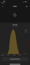
I have a new 8.4 Kw Tesla Solar Panel system (21 panels) with 2 PW+. It's been up and operational for over 2 months. The peak solar production I've ever seen this system produce is 5.6Kw and a total of 35.6Kwh so far. I live in Texas and we've had some pretty good sunny days and this is the peak I've seen this system generate. Is this normal? There are no obvious obstructions and the system is facing South (13 panel string) and West (8 Panel string).
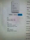
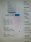
I used PyPowerwall to start digging into see if both strings are generating power properly and this is what I got from the string data:
Is it normal for the state of the second string to be 'PV_Active_Parallel'? Some of the other discussions I've seen on this forum have state as 'PV_Active'. Anyone familiar what parallel means for state of the string? And if this string data makes sense to you?
I used PyPowerwall to start digging into see if both strings are generating power properly and this is what I got from the string data:
JSON:
{'A': {'Current': 9.11, 'Voltage': 271.2, 'Power': 2449.0, 'State': 'PV_Active', 'Connected': True},

 'B': {'Current': 9.01, 'Voltage': 270.3, 'Power': 2400.0, 'State': 'PV_Active_Parallel', 'Connected': True},

 'C': {'Current': 0.0, 'Voltage': -1.0, 'Power': 0.0, 'State': 'PV_Active', 'Connected': False},

 'D': {'Current': 0.01, 'Voltage': -1.299999999999999, 'Power': 0.0, 'State': 'PV_Active', 'Connected': False}

 }
Is it normal for the state of the second string to be 'PV_Active_Parallel'? Some of the other discussions I've seen on this forum have state as 'PV_Active'. Anyone familiar what parallel means for state of the string? And if this string data makes sense to you?