I just recently finished installing an EcoHitch Trailer Hitch on my Tesla Model 3. I wanted to create a comprehensive write up about which hitch I chose, the installation of the hitch and wiring as well as the options I had for installing the trailer light wiring.
I have a November 2021 Tesla Model 3 with a birthdate of 10/31/2021. My M3 has a factory cutout in the bottom under shield plastic as well as the factory grey trailer plug.
I have a 750 pound 6x10 utility trailer that I want to be able to use sparingly. I wanted to install a trailer hitch as close to factory as possible without cutting anything or splicing into any wiring. I looked at both the EcoHitch and the StealthHitch because of the ability to remove the trailer receiver when not in use and allow the cutout cover to be reinstalled. I went with the EcoHitch because this uses a standard 2in square receiver that I can plug any hitch into whereas the StealthHitch requires you to use the hitch mount with the special interlock insert. Granted this does make for easier installation and removal which I will get more into at the end of the post.
EcoHitch
StealthHitch
For wiring I knew that my car likely had the grey trailer connector by looking at the wiring schematic for my car build date according to tesla service manual Trailer Connector X041. This connector has 12v power (red), ground (black), and CAN communication (violet). In Europe this connector is used to plug into the trailer ECU 1112581-00-A and then wiring harness 1446560-00-A is used to connect to the trailer. This wiring harness has a 13pin round European trailer plug on the end of it. Originally I was going to purchase the ECU and Trailer Jumper Wiring Harness from Tesla. I was then going to chop off the 13-pin European connector and wire in a US Flat 4 pin trailer connector while removing or capping off the extra wires. This proved to be too complicated due to the way the stop/brake lights use the same wiring as the turn signals on US trailers compared to trailers in Europe. I may follow up on this in more detail in a below comment.
I even made a service appointment with Tesla to get these two parts quoted and they were going to sell me these for about 70$. (Don't get me started on why I need to submit a service request to Tesla in order to purchase parts....) Please see the photo below for the quote.

From what I read if I installed the Tesla Trailer ECU, the ECU would work as expected to convert the CAN signals to the appropriate trailer light signals but the car would not have the option enabled in the software to activate trailer mode. Trailer mode disables a few features and limits certain functions as described by Tesla in the aforementioned link.
I was looking at what would be needed to convert a 13pin Euro connector to a US 4 Flat connector but discovered that this would need diodes and relays in order to have properly functioning trailer lights. I even purchased this adapter on amazon to try and reverse engineer how they are converting the signals from one connector to the other. This adapter looks like it would work but unfortunately everything inside is all potted and I cannot see the way the electronics are configured. I suppose I could have still used this adapter with the Tesla Trailer ECU and the Trailer Jumper Harness with 13pin EU connector. But I didn't want a bunch of connectors and adapters.
My dad actually found a Tekonsha T-connector harness that uses a 3 way pig tail connector on each tail light to grab the left turn/stop, right turn/stop and running light signals. This was perfect as I was able to just disconnect each of the taillight connecters, put this T connector harness inline and reconnect. No splicing or cutting wires necessary. Other modules that don't require cutting and splicing use no contact magnetic field sensors that clamp over each wire. These are nice but if the module looses power or power is connected with the vehicle lights already on then you need to perform a new learning procedure on the lights. Zero Contact Wiring Harness. The Tekonsha 118869 module that I used also needed power and ground. The instructions suggest that you use a ground bolt near the module for the white ground wire and run the black power wire under the length of the car and up under the hood directly to the positive of the LV 12v battery.
I then thought of the idea to use the factory grey trailer connector for power and ground. I was able to find the connector in the Tesla service manual X041. The connector reference guide gives you the part number for the connector. SUMITOMO 6189-0165 And from this I was able to find the opposite connector that I needed. I needed the male side part number 6188-0129. I was able to find this connector body with the pins and weather seals for only a couple of bucks on AliExpress. I was later looking at the StealthHitch installation instructions and saw that they mention doing this same thing when installing the towing option if your car is equipped with the grey connector from the factory.
Purchased the following:
1. EcoHitch from eTrailer eTrailer EcoHitch - 523$
2. Tekonsha T-Connector Harness 118869 Tekonsha 118869 - 120$ on eBay
3. Sumitomo XG7031B-4.8-11/21 Male Connector - AliExpress Sumitomo Connector $1.09 + 1.99 shipping from AliExpress
Did not purchase:
1. Assembly - Trailer Electronic Control Unit (1112581-00-A) - 36$
2. Assembly - Harness Trailer Jumper - NA (1446560-00-A) - 30$


Installation: Torklift EcoHitch Tesla M3 Installation Instructions PDF
1. Start by backing the car onto a set of ramps to give you access under the vehicle and to help raise the car to an ergonomic working height.
2. Open the trunk and remove the plastic trim piece at the bottom by pulling directly upwards.
3. Remove the plastic push locks by prying the center piece out. These release when the center piece is not fully pulled out but only partially.
4. Peel back the felt fabric on either side to expose the taillight connectors.
5. Pull the red locking tab out of each connector and then pull the connector to release this from the taillight housing
6. Use a 8mm socket to take off the two (2) nuts securing each taillight housing
7. Remove the trunk bump stops on each taillight housing by using a rag and an adjustable wrench
8. Carefully pull each taillight straight back to pull these out of their engagement (do not put sideways forced or angled pressure while removing these).
9. Remove each 10mm bolt that is exposed under each taillight housing.
10. Use a T-25 torx to remove each bolt in the rear wheel well that connects the corner of each bumper side to the fender
11. Remove 3 plastic push locks in each wheel well that secures the wheel well felt to the underbody shield
12. Underneath the car pop open the plastic covers on either side to expose a 10mm bolt.
13. Remove the six (6) 10mm bolts securing the plastic underbody shield to the frame.
14. With a helper start on the corners of each bumper side and lift up and away to disengage the bumper from the bumper clips. Start from the outsides and work inwards towards the center
15. Once the bumper is free; hold the bumper and reach in to release the ultrasonic sensors plug. You need to pull out the grey locking tab and depress the connector lock.
16. Put the bumper in a safe place without scratching the bumper. Be careful of the 2 nut clips on each corner of the bumper that secured the torx bolts
17. Remove the bumper clip bracket with five (5) 10mm bolts
18. Start removing the aluminum crash beam with a 15mm socket. This will be either five (5) or six (6) nuts.
19. Unbolt the two (2) aluminum plates with either six (6) or eight (8) 15mm nuts. Discard or save these plates.
20. Clean any NVH sealant that could be in the way of installing the hitch.
21. Mount the aluminum crash beam to the tow bar before installing onto the car. You may need to add a bolt or two to the tow bar depending on what your car came equipped with. Place the nylon washers over the studs between the crash beam and the tow bar. Use the original 15mm nuts to secure the crash beam to the trailer hitch. Tighten to 50 ftlbs.
22. Place nylon washers over the studs on the vehicle. Either six (6) or eight (8). Mount the tow bar and crash beam assembly to the car with 15mm nuts and tighten to 50 ftlbs. Be sure to center the crash beam and trailer hitch.
Continue with the wiring installation as described below before reassembly. Reassemble in reverse order. Be sure to catch the bumper underbody plastic underneath the front underbody plastic shield when reinstalling the bumper. Work from the center of the bumper outwards as you are reinstalling the bumper. Be careful of the nut clips on the corners of the bumper as you are pressing the bumper into the bumper clips. You may have to use your fist to "punch" the bumper into the clips with some force.
Installation Video
Torklift EcoHitch Tesla M3 Installation Instructions PDF
Wiring Installation - Tekonsha 118869 with power and ground from factory gray X041 Trailer Connector
23. Make up the male side of the gray connector for the power and ground wires. Be sure to slide the weather seal over the wire first. Then get a good crimp on the wire from the connecter pins. Make sure that you fully seat the connector pins until they click. Use the white connector insert to lock the pins in. The power and ground are on each side of the connector with the CAN signal in the center. Be careful that you don't short the power to ground on the vehicle.
I used a small amount of silicone and the third weather seal to seal off the center CAN bus connector hole as I did not use this wire and pin.
24. Crimp on the fuse holder to the power wire. Do not install the fuse yet to prevent any shorts.
25. I ran the power and ground wire in through the grommet on the passenger side of the vehicle. I cut an "x" into the grommet to get the wires through.
26. Once inside I ran these wires across the trunk and over to the drivers side and connected this to the Tekonsha Module.
27. I mounted the Tekonsha module to the inside metal of the car right below the drivers taillight.
28. The shorter yellow and brown T-connector wire was ran up to the drivers taillight and plugged in between the wire harness and the taillight
29. The longer green T-connector wire was ran across the trunk and up to the passenger taillight and plugged in between the wire harness and the taillight
30. I chose to install all the wiring inside 3/8" wire loom. I ran the 4 way flat connector wire form the module into the trunk. When using the trailer lights I will just run this wire out of the trunk and let the trunk lid close on the wire. (I chose to purchase an extension that I can run out of the trunk when in use and easily replace if this gets damaged).
31. Connect the harness to the taillights. Reinstall the fuse and test the lighting functions on the vehicle and the trailer plug.


Using the Hitch:
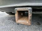
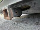
Each time you want to use the hitch you have to remove the plastic cutout cover and slide the 2in receiver up onto the tow bar. Then push the threaded bolt with lock washer and fender washer through the hole and tighten this into the captured nut using a 15/16 socket. This must be torqued to 112ftlbs before each use. The only issue I have is that it is very difficult to get a long torque wrench up into cavity onto the bolt head without hitting the ground. When the car is raised up with ramps this is not an issue as there is plenty of space to swing the wrench. I am still deciding on what is best to have on hand to do this easily without raising the car on ramps. This is where the StealthHitch is better as you can just put the hitch up into the space and the interlock catches the hitch.
I chose to add an extension to the 4 wire flat cable that I ran into the trunk cavity. The extension is there to let me put the wire out through the trunk lid and if this is ever damaged I can just replace the extension cable for cheap.
Overall this is an easy DIY project that can be done in a few hours once you have all the parts on hand.
The car tows like a dream. The instant torque of the EV makes it feel like there isn't a trailer behind you and the regen braking is really nice when towing compared to a truck. You naturally just let off the accelerator more to increase the regen power with the additional weight pushing on the car slowing down. I did create an additional profile with the parking sensors turned off, the car in chill mode and the steering set to standard.
The tow hitch only has a Trailer GVW of 2000lbs and a maximum tongue weight of 300lbs.

I have a November 2021 Tesla Model 3 with a birthdate of 10/31/2021. My M3 has a factory cutout in the bottom under shield plastic as well as the factory grey trailer plug.
I have a 750 pound 6x10 utility trailer that I want to be able to use sparingly. I wanted to install a trailer hitch as close to factory as possible without cutting anything or splicing into any wiring. I looked at both the EcoHitch and the StealthHitch because of the ability to remove the trailer receiver when not in use and allow the cutout cover to be reinstalled. I went with the EcoHitch because this uses a standard 2in square receiver that I can plug any hitch into whereas the StealthHitch requires you to use the hitch mount with the special interlock insert. Granted this does make for easier installation and removal which I will get more into at the end of the post.
EcoHitch
StealthHitch
For wiring I knew that my car likely had the grey trailer connector by looking at the wiring schematic for my car build date according to tesla service manual Trailer Connector X041. This connector has 12v power (red), ground (black), and CAN communication (violet). In Europe this connector is used to plug into the trailer ECU 1112581-00-A and then wiring harness 1446560-00-A is used to connect to the trailer. This wiring harness has a 13pin round European trailer plug on the end of it. Originally I was going to purchase the ECU and Trailer Jumper Wiring Harness from Tesla. I was then going to chop off the 13-pin European connector and wire in a US Flat 4 pin trailer connector while removing or capping off the extra wires. This proved to be too complicated due to the way the stop/brake lights use the same wiring as the turn signals on US trailers compared to trailers in Europe. I may follow up on this in more detail in a below comment.
I even made a service appointment with Tesla to get these two parts quoted and they were going to sell me these for about 70$. (Don't get me started on why I need to submit a service request to Tesla in order to purchase parts....) Please see the photo below for the quote.
From what I read if I installed the Tesla Trailer ECU, the ECU would work as expected to convert the CAN signals to the appropriate trailer light signals but the car would not have the option enabled in the software to activate trailer mode. Trailer mode disables a few features and limits certain functions as described by Tesla in the aforementioned link.
I was looking at what would be needed to convert a 13pin Euro connector to a US 4 Flat connector but discovered that this would need diodes and relays in order to have properly functioning trailer lights. I even purchased this adapter on amazon to try and reverse engineer how they are converting the signals from one connector to the other. This adapter looks like it would work but unfortunately everything inside is all potted and I cannot see the way the electronics are configured. I suppose I could have still used this adapter with the Tesla Trailer ECU and the Trailer Jumper Harness with 13pin EU connector. But I didn't want a bunch of connectors and adapters.
My dad actually found a Tekonsha T-connector harness that uses a 3 way pig tail connector on each tail light to grab the left turn/stop, right turn/stop and running light signals. This was perfect as I was able to just disconnect each of the taillight connecters, put this T connector harness inline and reconnect. No splicing or cutting wires necessary. Other modules that don't require cutting and splicing use no contact magnetic field sensors that clamp over each wire. These are nice but if the module looses power or power is connected with the vehicle lights already on then you need to perform a new learning procedure on the lights. Zero Contact Wiring Harness. The Tekonsha 118869 module that I used also needed power and ground. The instructions suggest that you use a ground bolt near the module for the white ground wire and run the black power wire under the length of the car and up under the hood directly to the positive of the LV 12v battery.
I then thought of the idea to use the factory grey trailer connector for power and ground. I was able to find the connector in the Tesla service manual X041. The connector reference guide gives you the part number for the connector. SUMITOMO 6189-0165 And from this I was able to find the opposite connector that I needed. I needed the male side part number 6188-0129. I was able to find this connector body with the pins and weather seals for only a couple of bucks on AliExpress. I was later looking at the StealthHitch installation instructions and saw that they mention doing this same thing when installing the towing option if your car is equipped with the grey connector from the factory.
Purchased the following:
1. EcoHitch from eTrailer eTrailer EcoHitch - 523$
2. Tekonsha T-Connector Harness 118869 Tekonsha 118869 - 120$ on eBay
3. Sumitomo XG7031B-4.8-11/21 Male Connector - AliExpress Sumitomo Connector $1.09 + 1.99 shipping from AliExpress
Did not purchase:
1. Assembly - Trailer Electronic Control Unit (1112581-00-A) - 36$
2. Assembly - Harness Trailer Jumper - NA (1446560-00-A) - 30$
Installation: Torklift EcoHitch Tesla M3 Installation Instructions PDF
1. Start by backing the car onto a set of ramps to give you access under the vehicle and to help raise the car to an ergonomic working height.
2. Open the trunk and remove the plastic trim piece at the bottom by pulling directly upwards.
3. Remove the plastic push locks by prying the center piece out. These release when the center piece is not fully pulled out but only partially.
4. Peel back the felt fabric on either side to expose the taillight connectors.
5. Pull the red locking tab out of each connector and then pull the connector to release this from the taillight housing
6. Use a 8mm socket to take off the two (2) nuts securing each taillight housing
7. Remove the trunk bump stops on each taillight housing by using a rag and an adjustable wrench
8. Carefully pull each taillight straight back to pull these out of their engagement (do not put sideways forced or angled pressure while removing these).
9. Remove each 10mm bolt that is exposed under each taillight housing.
10. Use a T-25 torx to remove each bolt in the rear wheel well that connects the corner of each bumper side to the fender
11. Remove 3 plastic push locks in each wheel well that secures the wheel well felt to the underbody shield
12. Underneath the car pop open the plastic covers on either side to expose a 10mm bolt.
13. Remove the six (6) 10mm bolts securing the plastic underbody shield to the frame.
14. With a helper start on the corners of each bumper side and lift up and away to disengage the bumper from the bumper clips. Start from the outsides and work inwards towards the center
15. Once the bumper is free; hold the bumper and reach in to release the ultrasonic sensors plug. You need to pull out the grey locking tab and depress the connector lock.
16. Put the bumper in a safe place without scratching the bumper. Be careful of the 2 nut clips on each corner of the bumper that secured the torx bolts
17. Remove the bumper clip bracket with five (5) 10mm bolts
18. Start removing the aluminum crash beam with a 15mm socket. This will be either five (5) or six (6) nuts.
19. Unbolt the two (2) aluminum plates with either six (6) or eight (8) 15mm nuts. Discard or save these plates.
20. Clean any NVH sealant that could be in the way of installing the hitch.
21. Mount the aluminum crash beam to the tow bar before installing onto the car. You may need to add a bolt or two to the tow bar depending on what your car came equipped with. Place the nylon washers over the studs between the crash beam and the tow bar. Use the original 15mm nuts to secure the crash beam to the trailer hitch. Tighten to 50 ftlbs.
22. Place nylon washers over the studs on the vehicle. Either six (6) or eight (8). Mount the tow bar and crash beam assembly to the car with 15mm nuts and tighten to 50 ftlbs. Be sure to center the crash beam and trailer hitch.
Continue with the wiring installation as described below before reassembly. Reassemble in reverse order. Be sure to catch the bumper underbody plastic underneath the front underbody plastic shield when reinstalling the bumper. Work from the center of the bumper outwards as you are reinstalling the bumper. Be careful of the nut clips on the corners of the bumper as you are pressing the bumper into the bumper clips. You may have to use your fist to "punch" the bumper into the clips with some force.
Installation Video
Torklift EcoHitch Tesla M3 Installation Instructions PDF
Wiring Installation - Tekonsha 118869 with power and ground from factory gray X041 Trailer Connector
23. Make up the male side of the gray connector for the power and ground wires. Be sure to slide the weather seal over the wire first. Then get a good crimp on the wire from the connecter pins. Make sure that you fully seat the connector pins until they click. Use the white connector insert to lock the pins in. The power and ground are on each side of the connector with the CAN signal in the center. Be careful that you don't short the power to ground on the vehicle.
I used a small amount of silicone and the third weather seal to seal off the center CAN bus connector hole as I did not use this wire and pin.
24. Crimp on the fuse holder to the power wire. Do not install the fuse yet to prevent any shorts.
25. I ran the power and ground wire in through the grommet on the passenger side of the vehicle. I cut an "x" into the grommet to get the wires through.
26. Once inside I ran these wires across the trunk and over to the drivers side and connected this to the Tekonsha Module.
27. I mounted the Tekonsha module to the inside metal of the car right below the drivers taillight.
28. The shorter yellow and brown T-connector wire was ran up to the drivers taillight and plugged in between the wire harness and the taillight
29. The longer green T-connector wire was ran across the trunk and up to the passenger taillight and plugged in between the wire harness and the taillight
30. I chose to install all the wiring inside 3/8" wire loom. I ran the 4 way flat connector wire form the module into the trunk. When using the trailer lights I will just run this wire out of the trunk and let the trunk lid close on the wire. (I chose to purchase an extension that I can run out of the trunk when in use and easily replace if this gets damaged).
31. Connect the harness to the taillights. Reinstall the fuse and test the lighting functions on the vehicle and the trailer plug.
Using the Hitch:
Each time you want to use the hitch you have to remove the plastic cutout cover and slide the 2in receiver up onto the tow bar. Then push the threaded bolt with lock washer and fender washer through the hole and tighten this into the captured nut using a 15/16 socket. This must be torqued to 112ftlbs before each use. The only issue I have is that it is very difficult to get a long torque wrench up into cavity onto the bolt head without hitting the ground. When the car is raised up with ramps this is not an issue as there is plenty of space to swing the wrench. I am still deciding on what is best to have on hand to do this easily without raising the car on ramps. This is where the StealthHitch is better as you can just put the hitch up into the space and the interlock catches the hitch.
I chose to add an extension to the 4 wire flat cable that I ran into the trunk cavity. The extension is there to let me put the wire out through the trunk lid and if this is ever damaged I can just replace the extension cable for cheap.
Overall this is an easy DIY project that can be done in a few hours once you have all the parts on hand.
The car tows like a dream. The instant torque of the EV makes it feel like there isn't a trailer behind you and the regen braking is really nice when towing compared to a truck. You naturally just let off the accelerator more to increase the regen power with the additional weight pushing on the car slowing down. I did create an additional profile with the parking sensors turned off, the car in chill mode and the steering set to standard.
The tow hitch only has a Trailer GVW of 2000lbs and a maximum tongue weight of 300lbs.