Welcome to Tesla Motors Club
Discuss Tesla's Model S, Model 3, Model X, Model Y, Cybertruck, Roadster and More.
Register

PG&E Green Meter Adapter with Powerwalls?

This site may earn commission on affiliate links.

slcasner

Active Member
Supporting Member
Feb 20, 2011
1,536
1,083
Sunnyvale, CA
In another thread I found the following post from @Vines that was the only search hit for Green Meter Adapter. That is a PV system connection option that PG&E offers; it's a cylinder that mounts to the meter socket and presents a new meter socket for the meter to attach to it. The key is that it provides a conduit attachment on the side of the cylinder so that the Gateway could be interposed between the meter and the main breaker on the existing panel to implement whole-house backup.
Green Meter Adapter Might be an option in this case, if you have underground service and your utility allows.

GMA is similar to a line side tap, but is special hardware that allows you to backfeed up to 60A of PV into the meter socket.
I've just placed and order for Solar Roof and have not had contact back from Tesla yet, but I'm trying to explore possible installation options for discussion with them and have just learned about the GMA. I have an old (1980) 100-125A combination meter box and distribution panel with underground service. Upgrading the panel would be difficult for several reasons, including that the service line is direct burial cable under the neighbor's yard. We would be replacing a PV system installed in 2000 that has a subset of circuits routed to the backed-up subpanel, but if we hooked the Gateway in there we'd have to meter all the non-backed-up circuits in the main panel and there's no way to gather them all into a couple of CTs (and no room for them, either). So whole-house would be a much simpler solution while providing its own advantages.

Questions:
  1. Does the Gateway 2 qualify for the role of "fused disconnect switch"?
  2. Is there a variation of the GMA where the conduit exits from the top rather than the bottom? That would allow a much more direct routing of the conduit since I don't have any wall space to the left of the meter.
  3. I believe we meet all the eligibility requirements except this one is not clear: "There are no existing customer generation sources on the property that are interconnected with the PG&E service. This could be in the customer distribution section (i.e., breaker or line/supply side connection) of the main panel or in a sub-panel. Multiple interconnections including battery storage systems will not be approved." Does that preclude having Powerwalls connected to the Gateway, or would the Gateway constitute a single interconnection?
 
In another thread I found the following post from @Vines that was the only search hit for Green Meter Adapter. That is a PV system connection option that PG&E offers; it's a cylinder that mounts to the meter socket and presents a new meter socket for the meter to attach to it. The key is that it provides a conduit attachment on the side of the cylinder so that the Gateway could be interposed between the meter and the main breaker on the existing panel to implement whole-house backup.I've just placed and order for Solar Roof and have not had contact back from Tesla yet, but I'm trying to explore possible installation options for discussion with them and have just learned about the GMA. I have an old (1980) 100-125A combination meter box and distribution panel with underground service. Upgrading the panel would be difficult for several reasons, including that the service line is direct burial cable under the neighbor's yard. We would be replacing a PV system installed in 2000 that has a subset of circuits routed to the backed-up subpanel, but if we hooked the Gateway in there we'd have to meter all the non-backed-up circuits in the main panel and there's no way to gather them all into a couple of CTs (and no room for them, either). So whole-house would be a much simpler solution while providing its own advantages.

Questions:
  1. Does the Gateway 2 qualify for the role of "fused disconnect switch"?
  2. Is there a variation of the GMA where the conduit exits from the top rather than the bottom? That would allow a much more direct routing of the conduit since I don't have any wall space to the left of the meter.
  3. I believe we meet all the eligibility requirements except this one is not clear: "There are no existing customer generation sources on the property that are interconnected with the PG&E service. This could be in the customer distribution section (i.e., breaker or line/supply side connection) of the main panel or in a sub-panel. Multiple interconnections including battery storage systems will not be approved." Does that preclude having Powerwalls connected to the Gateway, or would the Gateway constitute a single interconnection?
GMA will not do what you want, in many ways.

I'd recommend a like for like swap to a main breaker only MSP, the GMA will not be allowed to integrate with Powerwalls.

There may be other options if you post pictures of your panels.
 
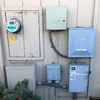
Here are pictures of the panels, J-box and disconnect switch, both outside and inside, and a construction photo from 5 years before the solar and EV charger were installed so it's missing some conduits coming out the bottom of the main panel. You can see that I am very space constrained. overview.pngequipment.pnginside-main.pnginside-jbox.pnginside-disconnect.pnginside-backup.pngconstruction.pngEdit: Sorry these thumbnails don't all show up properly but the images seem to be there if I click on the little boxes.
 
Definitely the irrigation box needs to move, but I'm not sure how another small subpanel would help me. I need to fit in the Gateway.

Also, I see now that I was thinking incorrectly about the GMA. It only allows the PV to be injected on the meter side of the main breaker, it does not allow something like the Gateway to be interposed between the meter and the main breaker. Probably because there is solid metal from the outside socket to the inside socket for all four posts.

Here's the label.
label-small.png
 
Drop in a compatible 100A branch circuit breaker into your Service panel and relocate all the loads to the new subpanel. Existing loads need to not more than 6' so put a small 100A or 125A panel next to the existing one.

Then down the wall a ways or inside the garage you install the PW themselves and the TEG, and send conduit from the MSP to the TEG, to the new backup loads subpanel.
 
But all the circuit drops would be on the other side of a stud from where the new panel would be (see the construction photo that's last in the list from my first photo collection). And the space to the next stud is only 8-10 inches, so the new panel couldn't be flush mounted to have the circuits enter through the top.

Maybe it would be possible to go vertical instead? If there's a short combination box with meter and main breaker that I could put down at the minimum meter height and then put a new main panel above it, that might work. What would be the height limit for the top of that new main panel?

The garage is miles away, but there's plenty of room for the TEG and Powerwalls further down the wall. In fact, there are concrete pads suitable for the Powerwalls already in place for the previous inverter and lead-acid battery box.
 
I'm wondering if the Span | A Smarter Electrical Panel panel would help? They claim that they can perform the function of the gateway, main panel and generation panel. I'm trying to get more information from them.

The Span product has no certifications to be compliant as an interactive disconnect for a grid tied system. Maybe down the road they will have that certification. Today they aren't claiming they can replace the TEG, just that it might be possible in the future.

But all the circuit drops would be on the other side of a stud from where the new panel would be (see the construction photo that's last in the list from my first photo collection). And the space to the next stud is only 8-10 inches, so the new panel couldn't be flush mounted to have the circuits enter through the top.

Maybe it would be possible to go vertical instead? If there's a short combination box with meter and main breaker that I could put down at the minimum meter height and then put a new main panel above it, that might work. What would be the height limit for the top of that new main panel?

The garage is miles away, but there's plenty of room for the TEG and Powerwalls further down the wall. In fact, there are concrete pads suitable for the Powerwalls already in place for the previous inverter and lead-acid battery box.

Minimum meter height is 44" Maximum breaker height is 6'7".
 
That link is no longer valid: "span.io has expired and is for sale on GoDaddy Auctions." Not a good sign for future developments.

Lol, forgot to pay those bills, oops. I saw a presentation from them and it does look like a cool product. Individual control and monitoring of every circuit in the panel is a cool feature. Will be watching them as they develop, and hoping they continue to evolve the product.
 
Minimum meter height is 44" Maximum breaker height is 6'7".
Thanks for all your advice here. Something like the pictured panel would allow fitting everything in the available space with the bottom at 36". The only problem is that I need the two sections in the bottom half to be swapped because the underground supply comes up in hard conduit on the left side.
tall-panel.png
 
Your approach seems harder, but maybe you see something I do not.

You have a bunch of surface mount equipment at the msp, why are you wanting a flush mount subpanel?
I'm not adding a subpanel, I'm replacing the existing MSP that is flush mounted. I guess a surface-mount main panel could also be used if it covers the hole. I'm not opposed to that. If the panel wiring is all redone with a new MSP then the existing backup subpanel and manual disconnect would be removed, but there would be other surface-mounted devices remaining and the TEG and inverter added.

Having the breaker section of the new MSP be higher on the wall than the old one would mean that the branch line wires would generally be long enough to reach the new breakers without splicing. As you may have noticed, there are many splices in my existing MSP installed to relocate a subset of the circuits to the backup subpanel.

Just reusing the subpanel from my existing solar installation or adding another subpanel would not work because there isn't enough room in the existing main panel to add metering. There are also benefits to backing up the whole house.

Would it be permissible to install a new panel with 200A capacity but just install a 100A or 125A main breaker if the buried service line cannot handle 200A?
 
Maybe we aren't connecting here. I thought you were trying to make a whole home backup work with that panel, maybe I didn't get it.

What I proposed was to gut the branch circuit breakers out of the MSP, but leave it physically in place:

-Install a 100A branch circuit breaker inside the MSP, and with that feed the TEG. I am assuming a 100A fits but I haven't checked. Bay Power would know for sure.
-Land all generation inside the TEG internal subpanel.
-Install new surface mount 100-125A subpanel with main breaker next to the existing MSP (or on the other side of the wall if that's agreeable with interior usage), extend all loads to land inside this new subpanel. You will have more splices but less breakers, it should work out.
Feed this new 100-125A subpanel from the other lugs in the TEG.

There are other ways to do this, but cutting service conductors and lowering the MSP is pretty serious, and not my first choice.

No you will not get away with a larger rated enclosure and a smaller breaker PGE doesn't like that at all.
 
  • Like
Reactions: arnolddeleon
Maybe we aren't connecting here. I thought you were trying to make a whole home backup work with that panel, maybe I didn't get it.
No, your're right. This would be a good goal.
What I proposed was to gut the branch circuit breakers out of the MSP, but leave it physically in place:

-Install a 100A branch circuit breaker inside the MSP, and with that feed the TEG. I am assuming a 100A fits but I haven't checked. Bay Power would know for sure.
-Land all generation inside the TEG internal subpanel.
-Install new surface mount 100-125A subpanel with main breaker next to the existing MSP (or on the other side of the wall if that's agreeable with interior usage), extend all loads to land inside this new subpanel. You will have more splices but less breakers, it should work out.
Feed this new 100-125A subpanel from the other lugs in the TEG.
Yep, I understand that method. That's Figure 21 in Appendix C of the Powerwall 2 Installation Manual. That would all be fine except the part that is unclear to me is how to get all the branch wires that come down inside the wall and through the top of the existing MSP out to the new subpanel that is next to the MSP on the other side of a stud.

I suppose that a J-box could be mounted on the surface above the MSP over an access hole that would allow pulling out all the wires and feeding them through the back of the J-box. That's similar to the big J-box we installed below the MSP as part of our existing PV installation. The wires would all need to be spliced in that J-box to reach the subpanel. A variation on this idea would be to mount the subpanel on the surface above the MSP instead of to the side. Its bottom edge would be at 59" which would give us 20" to the top breaker. Maybe a panel with two columns of breakers would fit.

Alternatively, you've suggested an idea I had not considered before to put the subpanel on the interior wall. That panel could be mounted flush in the same wall cavity where the wires are coming down, and since the home is on a raised foundation, a higher position for the panel would not be a problem. That would allow all the branch wires to reach the new breakers easily without splices. The only question is whether the interior location would be acceptable to certain parties. It is in the master bathroom where a large picture frame is currently hanging, so hiding it might be simple. Are there code restrictions on what kind of room a breaker panel can be in?
There are other ways to do this, but cutting service conductors and lowering the MSP is pretty serious, and not my first choice.
You're right, I was probably not giving that a strong enough consideration. It would involve a lot more downtime and interaction with PG&E.
 
No, your're right. This would be a good goal.Yep, I understand that method. That's Figure 21 in Appendix C of the Powerwall 2 Installation Manual. That would all be fine except the part that is unclear to me is how to get all the branch wires that come down inside the wall and through the top of the existing MSP out to the new subpanel that is next to the MSP on the other side of a stud.

I suppose that a J-box could be mounted on the surface above the MSP over an access hole that would allow pulling out all the wires and feeding them through the back of the J-box. That's similar to the big J-box we installed below the MSP as part of our existing PV installation. The wires would all need to be spliced in that J-box to reach the subpanel. A variation on this idea would be to mount the subpanel on the surface above the MSP instead of to the side. Its bottom edge would be at 59" which would give us 20" to the top breaker. Maybe a panel with two columns of breakers would fit.

Alternatively, you've suggested an idea I had not considered before to put the subpanel on the interior wall. That panel could be mounted flush in the same wall cavity where the wires are coming down, and since the home is on a raised foundation, a higher position for the panel would not be a problem. That would allow all the branch wires to reach the new breakers easily without splices. The only question is whether the interior location would be acceptable to certain parties. It is in the master bathroom where a large picture frame is currently hanging, so hiding it might be simple. Are there code restrictions on what kind of room a breaker panel can be in? You're right, I was probably not giving that a strong enough consideration. It would involve a lot more downtime and interaction with PG&E.

Sounds like the interior location may be a winner, there are no restrictions that I can think of since you can shut down all sources of power from the outside just fine. The only restrictions I can think of are working space issues, make sure the panel has 30" wide x 36" deep clear working space for inspection time. Subpanels can go in bedrooms no problem from a code perspective..
 
That link is no longer valid: "span.io has expired and is for sale on GoDaddy Auctions." Not a good sign for future developments.

Hmm, it worked last night when I posted it and it is working right now. I'm still quite skeptical but the promise sounds so good. I wish it was around a few years ago. I've done per circuit monitoring, I've done power backup and I had my 16 year old main panel replaced when we installed Powerwalls a couple of years ago. For range of prices they are quoting I might be better off adding a 3rd powerwall versus managing loads better. Although the recent sillyness with Santa Clara county fire rules might make that 3rd Powerwall harder.