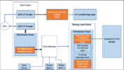
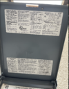
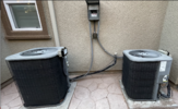
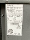
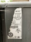
That is correct. All the loads on the main panel outside the house that I was expecting to be backed up having been relocated to a new panel they installed inside the garage, except for the EVSE.Thanks for the pictures. Per the markings on the dead front, the only "non-spare" breakers are a 90A for the A/C, a 90A for the GW, and a 40A for the EVSE. So two conclusions:
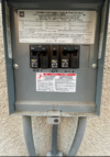
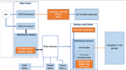
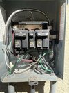
(1) Per the labeling, everything in the outdoor panel that you wanted backed up has been moved out to the newly installed Backup Panel. So if you believe otherwise, either (a) Tesla has mislabeled the dead front, and one of those breakers marked spare is still feeding a circuit or (b) the circuit that you are expecting to be currently backed up (because it had been in the main panel), but you find it isn't, you are mistaken and it actually originates in the garage panel. You can easily distinguish between the two possibilities by turning off all the "spare" breakers (right now the group at the upper left is off, but the two spares on the upper right are on, as are the spares at the bottom). If some circuit gets shut off, you know the issue is (a); but if nothing changes, then the issue is (b).
This is good know.(2) The above breakers total 220A, so Tesla has left you with a technical code violation. It's not actually a safety rule, as the NEC "sum of all breakers rule" is a bit stricter than physics requires. But it may be useful ammunition for negotiating with Tesla to get someone back to fix the mess they left.
Yes. They should have removed the stickers. I will do it.Oh, and those stickers at the bottom that say "Solar Breaker Do Not Relocate," but the breakers also say "Spare" on the Dead Front, those stickers are no longer accurate (assuming Tesla moved the solar to the internal panelboard in the Gateway as it was supposed to). So you can remove those or cross them out.
Now the real issue is, I am not able to get past the Project Advisor and talk to a design engineer to explain the situation. Whatever I tell the PA either verbally or communicate over email, seems to be getting lost in translation.Cheers, Wayne
All I heard from the PA is that their design engineer does not want to make any changes and it can only be solved by adding an additional PowerWall, which even if I wanted, they will not sell it to me

cheers and thanks for your help