Welcome to Tesla Motors Club
Discuss Tesla's Model S, Model 3, Model X, Model Y, Cybertruck, Roadster and More.
Register

Tesla installed strings in parallel on 7.6 Inverter

This site may earn commission on affiliate links.
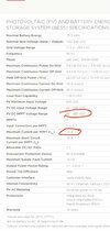
do you have 2 powerwall+ units for 36 panels? I have 36 panels, but 1 powerwall+ and additional powerwall2. My system is configured at 12kw, however, pre PTO, i see my solar power clamped at 7.6kw for 3-4 hours mid day, i have 3 mppts in use. Looking at the powerwall + spec sheet it looks like the max solar inverter power is 7.6kw, tesla claims this will get better once i recieve PTO but i don't see it in the spec sheet. I've gone thru the yearly estimations and if i'm truely limited at 7.6kw due to solar inverter i lose 5% of solar capacity thru the year due to clipping. Trying to figure out if my powerwall+ would support >7.6kw DC coming from 12kw array.
Yes I have two powerwall + units. I think the spec sheet answers this question pretty clearly. What is your panel orientation?
 

Attachments

  • 7BE2F875-DCD9-4D95-B4E7-93CD27726C85.jpeg
    7BE2F875-DCD9-4D95-B4E7-93CD27726C85.jpeg
    214.4 KB · Views: 222
Yes
And the results are in front of you, where same time, same orientation ...shading is making difference as published above
panel level is better ( original order ) than 4 string mppts vs 3 strings mppts vs 2 strings mppts

I just my feet down that i will not accept below 3 mppts for 24 panels period.

i think , I did the correct thing, as solar energy generation matters in a solar install. its not something to be unconcerned with.

i purchased a house specifically with large south facing roof with prefect angle, and look the "engineering design team" tried to install panels on the northside initially . nightmare for me. i did not seep well.

Like to hear what people think....if i was being unreasonable and demanding ....
Congratulations on getting Tesla to do the right thing and fix your install. Not unreasonable at all. I'm sure it took a lot of work and persistence on your part.
 
FWIW, putting two strings in parallel on a single MPPT is only going to negatively impact performance when the two strings have significantly different MPPT voltages. As long as the strings are the same length and orientation, only certain shading patterns will cause problems. Namely, when the optimal number of bypass diodes to be activated in each string differs, resulting in different MPPT voltages.

For example, if one string is completely unshaded, and one string is uniformly partially shaded, that's not a problem. All the PV cells involved are producing voltage; the partially shaded string will be producing less current, but Vmpp doesn't change much with insolation, so the two strings can operate at the same voltage reasonably efficiently.

But now suppose that one string is completely unshaded, and the other string has 1/4 of the panels illuminated at 40% and 3/4s of the panel illuminated at 80%. The latter string could either be operated with all panels producing voltage, and the current limited by the 40% illuminated panels, to provide 40% power. Or it could be operated with the less illuminated panels having their bypass diodes activated, so that only 3/4s of the panels are producing voltage, to produce 60% power. Which is what it would do on its own MPPT. But if it is paralleled with a fully illuminated string, it must operate at the same voltage with no bypass diodes activated, so it will end up producing only 40% power.

Cheers, Wayne

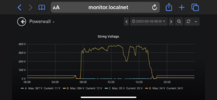
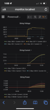
In my case I have two strings on the roof connected to a junction box and the inverter is pulling the voltage down in half (210v vs 380v) for both strings as soon as one string starts having shaded panels.

If it wasn’t for the junction box the system would perform great.
 

Attachments

  • 62B4EC35-E7ED-4896-8111-3649878CD443.png
    62B4EC35-E7ED-4896-8111-3649878CD443.png
    420.6 KB · Views: 135
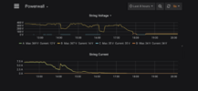
I think so by looking at the currents something funny is going on. The current has been dropping by 2/3 before this happens. At the time when the voltage dropped only 5 out of 22 panels (all on the same string) were shaded and before that even fewer.
 

Attachments

  • 609335A0-488B-4846-946F-B0F9C3716BE4.png
    609335A0-488B-4846-946F-B0F9C3716BE4.png
    228.5 KB · Views: 78
Yes but current and power drops before the voltage drops. At that time obly three panels were half shaded. Eventually the voltage drops to 200v, but by then it only recovers a small amount of power.
 

Attachments

  • F6B781D9-CB88-4AC0-994A-8C72A5AF7FDA.png
    F6B781D9-CB88-4AC0-994A-8C72A5AF7FDA.png
    374.2 KB · Views: 102
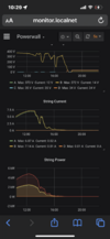
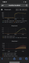
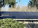
Another update with panel pictures this time. Today I caught it as the shading is starting. A tiny amount of shading in two panels is causing more than 10% production loss. The voltage has dropped more than 10% and the amps stayed roughly the same. It will get progressively worse from here.
 

Attachments

  • D5D8C1CB-737D-4784-8A04-940CCD9C16A6.jpeg
    D5D8C1CB-737D-4784-8A04-940CCD9C16A6.jpeg
    152.9 KB · Views: 105
  • F5062B15-0C0B-4DD0-9624-3CEE4769C341.png
    F5062B15-0C0B-4DD0-9624-3CEE4769C341.png
    396.2 KB · Views: 107
Half an hour later and production has collapsed to almost half. I think at this point the top MCI of the string that had the five panels partially shaded has taken the string out. Note that the voltage has not dropped to half yet.
 

Attachments

  • 1BF11EB1-5B8C-4B20-9877-C662352C3B4A.png
    1BF11EB1-5B8C-4B20-9877-C662352C3B4A.png
    408.3 KB · Views: 94
  • DB9162E9-2538-43E5-ACA7-2B4E67074C67.jpeg
    DB9162E9-2538-43E5-ACA7-2B4E67074C67.jpeg
    597.5 KB · Views: 133
The bottom line is that using a junction box to join two strings in the presence of partial shading is brain dead, especially when there are three unused channels on the inverter.
I agree with the above I just want to correct some information/terminology earlier in the thread. MCIs are safety devices only and don't play a part with panel shading and string optimization. If the inverters lose AC power the MCIs open the circuit in between panels so that dangerous DC voltages aren't generated on the roof.

There are multiple bypass diodes in each panel which deal with the shading issues and bypass sets of cells when they have more shading than other cells in string.
 
  • Like
Reactions: Vines
I agree with the above I just want to correct some information/terminology earlier in the thread. MCIs are safety devices only and don't play a part with panel shading and string optimization. If the inverters lose AC power the MCIs open the circuit in between panels so that dangerous DC voltages aren't generated on the roof.

There are multiple bypass diodes in each panel which deal with the shading issues and bypass sets of cells when they have more shading than other cells in string.
Tesla support mentioned something about MCI faults. This was the justification to send it to L2. So there may be a problem with them.

Also, the Tesla electrician told me that MCIs are optimizers (in writing). It sounded fishy but I thought they might be acting as bypass diodes at the panel level.
 
Tesla support mentioned something about MCI faults. This was the justification to send it to L2. So there may be a problem with them.

Also, the Tesla electrician told me that MCIs are optimizers (in writing). It sounded fishy but I thought they might be acting as bypass diodes at the panel level.
Exact quote:”We used MCI optimizers so it wouldn't matter if we Y connected on the roof or in the inverter.”

In any case something is not quite right. This small amount of shading should not crater production.
 
Quick update. It tools three+ months of calls every other week and multiple emails with voltage data to get Tesla to fix the design and redo the wiring. Unfortunately, it is a rainy day and I cannot asses the impact it yet.

It is pulling them off the powerwall+.
 
I'm really beginning to wonder where the engineers at Tesla got their degrees. I have a 24 panel setup - 12 East, & 12 West, with no shading, yet while they series wired the East side, they parallel wired the West side. (On the West side they split the panels 6/6, only 1 foot apart for a vent.) I asked why they didn't just do both series and the answer was "The engineer drew it that way." Of course, this is just part of my problems - Unconnected arrays, DC Arc Faults, and now the System won't even power up, showing inverter problems. (And no indication what they plan to do about it or when they'll return to fix it.)

View attachment 708384
Mine looks exactly like this. Don't know why, or if it's good or bad, just a data point.

Tim