Welcome to Tesla Motors Club
Discuss Tesla's Model S, Model 3, Model X, Model Y, Cybertruck, Roadster and More.
Register

RGB Ambient Lighting project for Palladium Model S - lets do it

This site may earn commission on affiliate links.
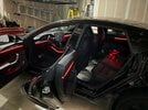
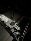
Really awkward picture angle BUT i got the footwell lights hooked up and working. Stupid me burnt one of the strips out as i attempted to pass 12v into the 5v strip, but a quick USB buck converter, a 2.5mm barrel jack splitter, and a usb to 2.5mm barrel jack power connecter fixed that right up.

Parts list for the footwell lights:
Ws2811 Controller, SP110e... Amazon.com
DROK 12V to 5V DC USB Buck... Amazon.com
LOAMLIN WS2812B Individually... https://www.amazon.com/dp/B09577D22S?ref=ppx_pop_mob_ap_share
Vrabocry 5pcs 15cm 3pin SM... Amazon.com
2 pcs/pack 3M 9.84ft 3 Pin JST SM... https://www.amazon.com/dp/B07G7X61W3?ref=ppx_pop_mob_ap_share
Belker Universal 5V DC Power... https://www.amazon.com/dp/B09DCL56XM?ref=ppx_pop_mob_ap_share

And then the barrel jack y splitter, which i got from a local electronics store.
 

Attachments

  • 56F1DAFE-4DE5-42C1-9EE4-2BF00CDA9D8B.jpeg
    56F1DAFE-4DE5-42C1-9EE4-2BF00CDA9D8B.jpeg
    301.8 KB · Views: 23
I heavily taped the wires to a broken piece of the LED strips i was using and used that as a pull tool. Push it through the back of the grommet from the door side until you can pull it through the driver footwell, then use strong tape (i used electrical) to seal the wire to the led strip, then pull it back through.
Thanks for the tip, and I will do that.

However, I am referring to the firewall grommet, that goes from under the drivers dash to under the hood. There is a good audio-video shop near me who have done a lot of work on Teslas. They said they can pull some wires for me.
 
There have been a few that have successfully run the strips between the chrome and the side panel of the console and a few who have been unsuccessful.

It looks like the tolerance is so close that the wall panel cannot snap back into place. Any tips from those that have had success would be well enjoyed !!
 
Half way there. 8 hours? No way, the first door is a bi*ch. second door easy!! I do have some insights that I will share tomorrow. Thanks for all the help and guidance, special thanks to @Proppilot for the details and to @vcor for the Tesla tap info, ended up getting the tap adapter and made it easy to power the controllers. I spent10 hours today and I expect to spend another 8 tomorrow.
Can't see any of your pics.
What made the door install so difficult? Any tips appreciated.
 
There have been a few that have successfully run the strips between the chrome and the side panel of the console and a few who have been unsuccessful.

It looks like the tolerance is so close that the wall panel cannot snap back into place. Any tips from those that have had success would be well enjoyed !!
The one time I actually wanted Tesla panel gaps, they're not there 😂
 
  • Funny
Reactions: 4SUPER9
HI all, I'm currently at work so I can't post pictures (wont be able until tomorrow as I'm going to a friendly poker tourney tonight), I spent about 20 hours this weekend on the project and I do have some pointers. Footwell ambient light is always on, the brightness is what varies when you turn on/off the ambient lights from the screen, thus making the relay circuit unviable, at least with the current relay module that I have (any helps from the experts on this matter is needed and appreciated).

For the center console I spent about 2 hours... those are extra tight, there are almost no gap to place the strip (please note your specs might vary). In my case I did the driver side first, partially removed the side panel so I had access and using the double sided tape glued the strip to the chrome trim, I attempted after to snap the panel back in place but this was IMPOSSIBLE (not enough clearance). I gave up and moved to the passenger side this time to attempt and do it without glue tape, I, again partially removed the side panel, and as I was slowly snapping it back inside I was pushing in place the led strip, this was so much time and effort consuming, but got a perfect flush (It will be sad if I had to open that panel again). Lesson learned went and did over the driver side with no glue and was able to snap the trim back in place. So conclusion is as ridiculous as it may sound the extra thickness from the glue tape is enough to prevent you from having enough clearance to snap the side console back in place. (again please consider you may have a little bit more room and you might be able to use the glue tape and still close the center console).

The first door is your teacher, you will have to endure it, and in my case (my teacher was so beautiful) Ill have to do it again (once I do the bin lights).

While getting access to the back door, on the B pillar, I pulled the carpet trim as per the instructions on service.tesla.com, but instead of the clips releasing, the carpet came apart from the plastic that has the clips. I then realized the two pieces were glued with hot glue so I eventually used the heat gun to make the glue active again and made pressure from the carpet against such piece.

thanks again @Proppilot for making this thread and the contributions
 
  • Informative
Reactions: 4SUPER9

This is the link to the guy that designed a simple circuit to control the ambient lights from the screen. If they are not going off when they are 'off' then I believe Tesla is using PWM (pulse width modulation) to vary the lighting intensity and why your relay is buzzing. To a relay, PWM would almost look like AC that would be alternating ON and OFF. That is my theory. I will play with it this weekend and come back with a solution. It may be as simply as a filter capacitor on the input leads. Now I know why third parties have not been able to offer Palladium interior lighting retrofits. They have tried and toiled and no cigar and likely because Tesla used the light tubes and modulated LEDs to illuminate them with marginal lighting coming from them unless it is pitch black.

This is his circuit. He takes the power from the 12 v (actually 15 v) power plug and triggers from the footwell light signal. NOW....this is for a Model 3 which may not have the system we have (and I suspect not at this point as I have gotten deeper into the project).

I am not to be deterred ! I want to turn mine on and off from the screen !! Back to it.

1711403065184.png
 
Brief of my setup
.

This shows more progress with the relay as I hooked to the driver's bin light
I might consider doing the under console and under seats next, but for now I'm DONE.

Things I learned....
Removing the bin light connectors is tricky, specially the ones on the right hand side as the connectors are not position inverted, meaning that is really hard to squeeze your hand to press the connection I suggest you use a paper clip or something of the sort. if you use a clip insert it where the no 2 arrow says. if using your hands, you have to press the tab and then pull. the first one took me about 10 minutes to remove, sub-sequent were easier until I faced the right hand side of the car.

For the power access, I tapped into the tray connector, I first put solder on the tips of the cables I used making them like pins, then I removed the green part of the tray connector and I fit in the cables I soldered piggybacking the ones in the connector. I used a barrel connector against those and a barrel plug on the other side, this way connecting disconnecting everything in case you need to check/modify is done a lot easier.

On the downside, with this setup, I believe the lights will remain on if the car is in sentry mode

IMG_8407.jpeg

IMG_8408.jpeg
binlightpin.png
 

Attachments

  • IMG_8409.jpeg
    IMG_8409.jpeg
    358.8 KB · Views: 8
  • IMG_8392.jpeg
    IMG_8392.jpeg
    279.3 KB · Views: 7
Last edited:
One more thing I forgot to mention, 2 kits its definitely a most
@taekua : Beautiful! Thank you for sharing.
So, it looks like the relay works, but is just buzzing upon activation. I wonder if a different relay module may work better.
I ordered a different relay, just in case I got a bad one, or I messed it up when connected to the driver's foot light
I wont be able to test it until Monday as I'm off to the snow next few days. Fingers crossed it will work, but at this point I can only do trial an error, I'm not that advanced in electronics
 
One more thing I forgot to mention, 2 kits its definitely a most

I ordered a different relay, just in case I got a bad one, or I messed it up when connected to the driver's foot light
I wont be able to test it until Monday as I'm off to the snow next few days. Fingers crossed it will work, but at this point I can only do trial an error, I'm not that advanced in electronics
Ha! I just came back from Utah and nearly killed myself skiing double blacks in the trees with my son. He definitely showed me up!
 
I just opened the LEDs from Aliexpress. The instructions say that the input is 6-18v, output 5v. Therefore, it seems like we should not require a step-down/buck converter, right? My power source is actually already stepped-down, so it makes no diff to me, but trying to contribute to the group.
 
I just opened the LEDs from Aliexpress. The instructions say that the input is 6-18v, output 5v. Therefore, it seems like we should not require a step-down/buck converter, right? My power source is actually already stepped-down, so it makes no diff to me, but trying to contribute to the group.
Definitely check your documentation. Looks like you are good without a BUCK. My controllers say 8-14 volts so I am taking the BUCK route.

As for the relay, tomorrow I am going to do some experimentation with mine in my car. I will check the signal to the lamp with my scope as I suspect it is PWM and not straight DC and will see if something as simple as a capacitor across the input can settle it down. I NEED SCREEN CONTROL !!!

@taekua your install looks AMAZING. GOSH I cannot wait to be done this to enjoy the glow
 
For the power access, I tapped into the tray connector...
This is one of the best places to tap into power, as it is easily accessible and a reasonable amount of power is available. It does remain on if sentry mode is on, but for some projects, that's a good thing. I sort of like having the lights on with Sentry mode on. The amount of power is not that significant either for lighting.

I found all the connectors and pins if you want to make a removable connection and documented all the part numbers here: Power Tap – TeslaTap Here is my video for getting access to the phone charger connector:

I also sell power tap adapters that insert between the phone charger connector and the Tesla wire harness if you don't want to make your own or cut into Tesla wires.
 
One thing I'm noticing is that the glue on the strips doesn't seem strong enough, with different kits I got different tapes, one was yellowish color super thin, not holding good for the front door, the other tape was transparent also having problems holding, I bought 3M tape but its black, so if there is any visible gap between the led strip and the trim it looks aesthetic. @Proppilot Which kind of adhesive are you using ?
 
Removing the bin light connectors is tricky, specially the ones on the right hand side as the connectors are not position inverted, meaning that is really hard to squeeze your hand to press the connection I suggest you use a paper clip or something of the sort. if you use a clip insert it where the no 2 arrow says. if using your hands, you have to press the tab and then pull. the first one took me about 10 minutes to remove, sub-sequent were easier until I faced the right hand side of the car.
I believe @Proppilot mentioned upthread that because the new LEDs are so much brighter, one could leave the original bin lights in place. I would tend to believe that, given that I barely can see them, even when it is really dark. Do you think leaving the original lights on would interfere with the quality of the replacement LED's?
 
Definitely check your documentation. Looks like you are good without a BUCK. My controllers say 8-14 volts so I am taking the BUCK route.
Very interesting. I just took another look. The controllers clearly says 8-14V, while the documentation clearly says otherwise, listing 6-18V. I am going to stay safe and stick with what the controller says, and use my step-down.

Voltage.jpg
 
One thing I'm noticing is that the glue on the strips doesn't seem strong enough, with different kits I got different tapes, one was yellowish color super thin, not holding good for the front door, the other tape was transparent also having problems holding, I bought 3M tape but its black, so if there is any visible gap between the led strip and the trim it looks aesthetic. @Proppilot Which kind of adhesive are you using ?
my kits came with a roll of clear very narrow VHB tape. No glue on my strips as supplied