Welcome to Tesla Motors Club
Discuss Tesla's Model S, Model 3, Model X, Model Y, Cybertruck, Roadster and More.
Register

Shocked from gutters after Solar Roof activated

This site may earn commission on affiliate links.
I see your meter can measure the AC voltage frequency. Perhaps you can check it and it might provide more clues. It seems odd that RSD would send AC over the DC lines.

Is there any DC voltage between the tile and earth?
I've checked it, I've gotten these readings:
- Flashing to house outlet ground 50.3 VAC
- Flashing to aluminum ladder with plastic feet 60.7 VAC
- Nail in chimney to house outlet ground 74.0 VAC (yes, you read that correctly)

DC voltage is in the mili volt range, so basically zero on above three. I can't actually reach a photovoltaic panel easily, and wouldn't expect a reading anyway, as it's all glass beyond the backing I can't reach.
 
According to testmeterpro.com "The Klein MM200 is one of Klein’s lower end multimeters." so it sounds like I have some shopping to do! :) Any recommendations?
No, I don't actually have a low impedance meter or know much about them. I just know that when chasing voltages like this, the reading you get on a high impedance meter may be due to capacitive or inductive coupling, and that it wouldn't actual shock you (beyond something like you get from a static build-up) as it couldn't provide any sustained power. A low impedance meter would give a different reading in that case.

I think it's also the case that you could get a similar effect by attaching an appropriate load across your current meter's two probes, although I'm not sure what an appropriate load would be.

If you research either of these questions and come up with something, please share.

Cheers, Wayne
 
From what I saw in the install, the panel tiles are isolated in the center of the roof, edged by either glass or metal tiles, which then tie into a metal edge detail around the entire surface. All connectors are "plug and play" from what I saw, so very unclear how any of the DC circuitry or tiles would be directly electrically connected. The entire issue also is AC, not DC, and so seems to be related to induction vs a short.

Video of the voltage pen:

Is there a metal fireplace insert or flue? Had you ever tried the pen on the fireplace brick before the PV install? That part is just odd, although not really if there were installed AC wiring behind the brick or walls.

I curious about your 5800 pic. Is that center front facing wall, which looks almost vertical, installed with active tiles? (Not related to your problem, just didn't know they did that, if true.)

I re-read your first post... You mention waiting on a meter and being off-grid? So is your system not connected at all to the main presently? Was everything else wired as far as you know from Tesla? I wonder if there is an actual grounding problem at the main panel/PV side.
 
Last edited:
@wwhitney would connecting a wire from the gutter to ground (I.e. low impedance) and then measuring with a clamp meter the current work?
I would think that would be too low impedance. You would want to connect a ~10-100k resistor between the gutter and ground and measure the voltage drop across the resistor to stimulate a low impedance meter.

I'm not sure exactly how this would really help tracing down the issue though.
 
Is there a metal fireplace insert or flue? Had you ever tried the pen on the fireplace brick before the PV install? That part is just odd, although not really if there were installed AC wiring behind the brick or walls.

I curious about your 5800 pic. Is that center front facing wall, which looks almost vertical, installed with active tiles? (Not related to your problem, just didn't know they did that, if true.)

I re-read your first post... You mention waiting on a meter and being off-grid? So is your system not connected at all to the main presently? Was everything else wired as far as you know from Tesla? I wonder if there is an actual grounding problem at the main panel/PV side.
The fireplaces are masonry, no metal insert, and may have some metal for structurally tying things together, but overall are just huge masses of dielectric material. My guess is that they are acting like a capacitor somehow. I have two chimney's, four fireplaces (1st and 2nd floor, both sides of the home). Both exhibit this phenomenon and trigger the tester, on both floors. If I shut down the PV system by turning off the inverter breakers, the signals in the walls, celling, chimney, flashing all go away. So their isn't some legacy AC circuit related to the issue. It seems strictly related to the PV.

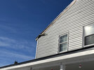
The 5800 pic is the vertical wall with the dormers, this wall is strictly glass and metal. The closest active tile to that location is the roof above that wall in the MP7 zone. The MP3 zone is also completely separate electrically from both a roof/PV and flashing perspective. The MP3 zone also exhibits flashing that carries a voltage. The 6 other zones are all electrically connected by flashings. The only way in which these two zones are connected is the hard metal conduit on the DC feeder lines, and that metal is grounded at the inverter to house ground. This grounding ends at the junction boxes right before the roof penetration, and I do not believe the roof or flashings are linked to this one ground source.

I am currently off grid and not yet backfeeding. My utility inspection was 12/28/21, and I'm still waiting on the utility to upgrade me to a net metering meterbase. My batteries have also never been fully charged yet, so I'm not in a state where the system is rate limiting due to lack of load.

Although I have a 30.5kW system, the max output I've seen so far is 5kW (instantaneous) / (20.5kW over 9 hrs sunlight), as only zones 3, 6 and 7 currently get any direct sun at this time of year. They total 18.1kW. Upon commissioning the system, Tesla's quality team thought there was a wiring issue because of the low production rate, came out and re-inspected the inverters, made some changes to CT's and then chalked it up to shading instead. (I still have some trees to remove).

Based on production rates and this voltage issue, I personally believe something might still be wired wrong.

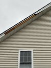
Also note, I'm not the original poster of this thread, I just have a very similar situation, and if I had gutters at the moment, I would also expect them to be electrified. Originally I was going to install copper gutters, but this issue now has me greatly concerned that there is a galvanic corrosion issue of dissimilar metals when dealing with a roof like this.
 
Last edited:
The only way in which these two zones are connected is the hard metal conduit on the DC feeder lines, and that metal is grounded at the inverter to house ground. This grounding ends at the junction boxes right before the roof penetration, and I do not believe the roof or flashings are linked to this one ground source.
Have you checked if there is a voltage on the conduit coming from the inverter? I know it should be grounded at the inverter but maybe the ground is bad? Check the potential relative to a known good ground.
 
Have you checked if there is a voltage on the conduit coming from the inverter? I know it should be grounded at the inverter but maybe the ground is bad? Check the potential relative to a known good ground.
Tesla's Quality Engineer have checked. I've checked via my hand. That is not the issue.

The issue seems to be with software and the way the inverters work. I've confirmed with the technician that they send an AC signal over the DC feeds to the Mid-Circuit Interrupters (MCIs) which functions as a Rapid Shutdown Devices. It is believed that the tuning of the inverter signal builds up a charge. It's also been confirmed that the DC side is unground, on purpose, as a ground would solve this, but also leak power. It is designed as an ungrounded DC system to maximize efficiency.

We are currently rolling back from software version 44 to 39 to validate. Hope to have an answer today.
 
  • Like
Reactions: cobra
BLUF version: Inverters sent enough electricity to gutters to shock me while cleaning. Solved with firmware update?

Our solar roof was installed in May 2021 but inverters not turned on until Oct while awaiting PTO. Tesla did not remove or switch out the existing gutters during install.
At the end of October I was doing my end of leaf season gutter scleaning when I realized one of the gutter section would shock me every time I reached in. I then checked with a Klein non contact voltage tester (NCVT-2) and that gutter was causing it to start beeping 4 inches out. Then I noted all of my gutter downspouts at ground level also was causing the tester to activate 3-4 inches out. Then I noted that my son's bedroom window which is at roof height was setting off the tester from a 4 inch distance. Nothing around the inverters or 2 Powerwalls caused the tester to activate.
When the sun went down no voltage was detected at those spots. I was not smart/interested enough to just shut off the inverters during daylight to test whether there was detectable voltage.
After much scouring of TMC/Reddit/internet to see if there was any post mentioning something similar I gave up and put in a service request 11 Nov mainly to figure out if this was a dangerous or normal situation. Today (13 Dec) the Tesla electrician spent 4 hours at the house (mostly on tech support with the engineers) and ended up updating the firmware of the inverters. He said the voltage now should be at a level that is safe and he said he did not get shocked when he touched the gutters. There was no mention of miswiring.
The non contact voltage tester still goes off near the gutter downspouts at ground level. I will wear rubber gloves when I clean the gutters in the Spring after pollen/tree flowering season.

I figure we are all beta testers with the solar roof and wanted other users to know of this possibility.

Still confused how my NCVT-2 which is supposed to only detect alternating current is going off when the solar tiles should be just producing direct current.
Chucklesn,

The Technician has indicated that he's only seen this issue when the system contains a Tesla Inverter. I have two Powerwall+ with DC coupled inverters and then one stand alone. Do you have one of these?

This device:
 
End of day here, Tesla has rolled back to version 21.44 and for now it's being considered "fixed". There is still a voltage detectable in the flashing, but little to no current. The AC Voltage is from the signals sent over the DC circuits, for how the MCI's work. Since we passed the "touch test", its considered complete, and I just plan to turn the system off should anyone be doing maintenance on the house near the roof to be extra safe.
 
I've confirmed with the technician that they send an AC signal over the DC feeds to the Mid-Circuit Interrupters (MCIs) which functions as a Rapid Shutdown Devices. It is believed that the tuning of the inverter signal builds up a charge. It's also been confirmed that the DC side is unground, on purpose, as a ground would solve this, but also leak power. It is designed as an ungrounded DC system to maximize efficiency.
I find this explanation suspect. Calling the DC side ungrounded is not very accurate. The current terminology in the NEC is "functionally grounded." The details are a bit complicated, and I'm not sure I've got the following 100% correct:

A couple decades ago, the DC side had one conductor solidly grounded. The inverter would then create a two wire AC power source in which one leg was grounded. That's different than the 120/240V split phase 3-wire residential system, so the inverter would include a 240V : 120/240V transformer. [Actually with a transformer, there's no reason the initial inverter AC voltage has to be 240V, so not sure what was used.]

Modern transformerless inverters do things a bit differently. The AC side is directly connected to the +120V and -120V legs of a 120/240V split phase service; there is no transformer providing isolation. Since the AC side has its midpoint ground referenced, the DC side ends up with its midpoint ground referenced (as I understand it), but there is no solid connection from the DC side to ground. Since there is no longer isolation between the DC and AC sides, there are AFCI/GFCI type detectors on both sides to shut things down if there's a ground fault.

Cheers, Wayne
 
  • Informative
Reactions: BGbreeder
Chucklesn,

The Technician has indicated that he's only seen this issue when the system contains a Tesla Inverter. I have two Powerwall+ with DC coupled inverters and then one stand alone. Do you have one of these?

This device:
Correct,

I have 2 Tesla inverters… one 3.8kW and one 7.6kW with two Powerwall 2 for storage.

Thanks much for the write up!
 
I find this explanation suspect. Calling the DC side ungrounded is not very accurate. The current terminology in the NEC is "functionally grounded." The details are a bit complicated, and I'm not sure I've got the following 100% correct:

A couple decades ago, the DC side had one conductor solidly grounded. The inverter would then create a two wire AC power source in which one leg was grounded. That's different than the 120/240V split phase 3-wire residential system, so the inverter would include a 240V : 120/240V transformer. [Actually with a transformer, there's no reason the initial inverter AC voltage has to be 240V, so not sure what was used.]

Modern transformerless inverters do things a bit differently. The AC side is directly connected to the +120V and -120V legs of a 120/240V split phase service; there is no transformer providing isolation. Since the AC side has its midpoint ground referenced, the DC side ends up with its midpoint ground referenced (as I understand it), but there is no solid connection from the DC side to ground. Since there is no longer isolation between the DC and AC sides, there are AFCI/GFCI type detectors on both sides to shut things down if there's a ground fault.

Cheers, Wayne
So the other thing about the stand alone inverter is that it doesn't have a neutral on the AC side. Only the two powerwall plus inverters have an AC neutral. I'm not sure how that factors in but it was something the Tech explained that went over my head.
 
  • Informative
Reactions: cobra
We are experiencing a similar issue with our Tesla Solar Roof (15kw with two Powerwall 2+). Our siding contractor attempted to remove the facia trim (see photo) and was shocked several times. He is fine, but it was enough to startle him. The whole system is now off while we wait for Tesla to schedule someone to come look at it. Our system is not grid activated yet (still waiting after 4+ months) so maybe we're seeing the A/C shut-off signal? I'm not sure if the battery was full, but its possible, as it was in the afternoon. Or do you think this is an induction issue, a short, or a ground issue? Unfortunately I don't have a voltage reading to share.
 

Attachments

  • IMG_6186.jpeg
    IMG_6186.jpeg
    637.6 KB · Views: 86
  • Informative
Reactions: cali8484
We are experiencing a similar issue with our Tesla Solar Roof (15kw with two Powerwall 2+). Our siding contractor attempted to remove the facia trim (see photo) and was shocked several times. He is fine, but it was enough to startle him. The whole system is now off while we wait for Tesla to schedule someone to come look at it. Our system is not grid activated yet (still waiting after 4+ months) so maybe we're seeing the A/C shut-off signal? I'm not sure if the battery was full, but its possible, as it was in the afternoon. Or do you think this is an induction issue, a short, or a ground issue? Unfortunately I don't have a voltage reading to share.
I wish I knew what was going on with these but I do not.

Start with a multimeter I'd say and see if it is a DC or AC voltage and what is the magnitude.
 
Went through this about six months ago and learned a lot.

System is 21Kw solar roof with six powerwalls and three Tesla inverters.

Gutter guys came over and two installers received an electrical shock. We determined that the entire roof was hot on all four sides.

Tesla updated the firmware which did not help.

Power readings with a meter were AC anywhere from 10 to 40 volts. Current was in the 10 to 200 milliamp range and varied constantly.

After a massive amount of time and effort it was determined that the issue happened only when there was sunlight. This ruled out power entering the roof from an external source. It was also determined that it occurred regardless of which Inverter was online. We also determined that the output of an inverter had to be greater than approximately 4200 watts.

Some guy from Tesla support stated that this is similar to what happens during commercial power generation where static electricity is generated as a by-product of producing power.

After recognizing the small risk of serious injury since the voltage and current was so low the system was shut down during gutter install and then recommissioned when they were finished.

I still have the issue today and had forgotten about it until I saw this thread.
 
  • Like
  • Informative
Reactions: griffd and cali8484
We are experiencing a similar issue with our Tesla Solar Roof (15kw with two Powerwall 2+). Our siding contractor attempted to remove the facia trim (see photo) and was shocked several times. He is fine, but it was enough to startle him. The whole system is now off while we wait for Tesla to schedule someone to come look at it. Our system is not grid activated yet (still waiting after 4+ months) so maybe we're seeing the A/C shut-off signal? I'm not sure if the battery was full, but its possible, as it was in the afternoon. Or do you think this is an induction issue, a short, or a ground issue? Unfortunately I don't have a voltage reading to share.
Same exact issue - had to replace facia trim just like yours that the wind blew off in the storm today and the contractor was shocked. It was pretty cloudy which makes me really wonder what the heck is going on. I’m going to call Tesla after the holiday weekend.
 

Attachments

  • E329A9AF-D6C9-49AF-8239-6AD4588A2CF9.jpeg
    E329A9AF-D6C9-49AF-8239-6AD4588A2CF9.jpeg
    387.9 KB · Views: 30
Went through this about six months ago and learned a lot.

System is 21Kw solar roof with six powerwalls and three Tesla inverters.

Gutter guys came over and two installers received an electrical shock. We determined that the entire roof was hot on all four sides.

Tesla updated the firmware which did not help.

Power readings with a meter were AC anywhere from 10 to 40 volts. Current was in the 10 to 200 milliamp range and varied constantly.

After a massive amount of time and effort it was determined that the issue happened only when there was sunlight. This ruled out power entering the roof from an external source. It was also determined that it occurred regardless of which Inverter was online. We also determined that the output of an inverter had to be greater than approximately 4200 watts.

Some guy from Tesla support stated that this is similar to what happens during commercial power generation where static electricity is generated as a by-product of producing power.

After recognizing the small risk of serious injury since the voltage and current was so low the system was shut down during gutter install and then recommissioned when they were finished.

I still have the issue today and had forgotten about it until I saw this thread.
What would happen if you ground the gutters via a copper cable to ground?