Not to start a debate (and it's certainly
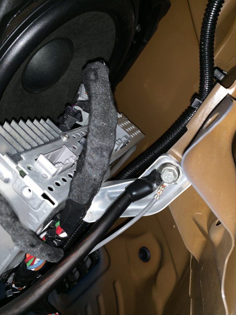
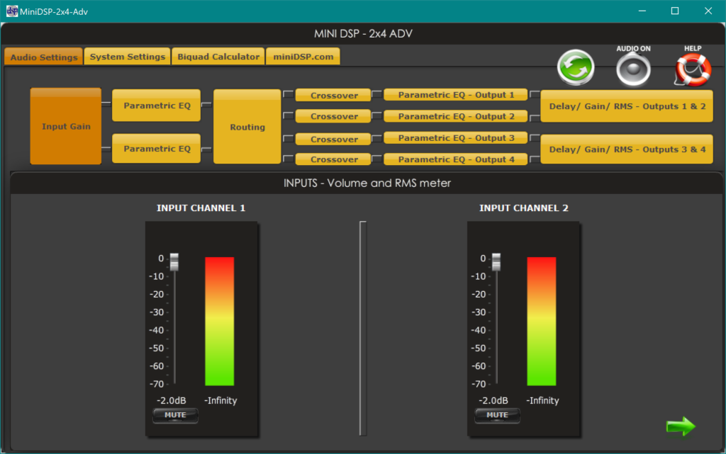
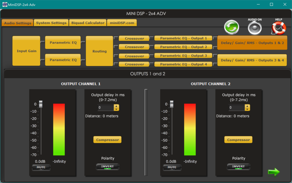
not my intention to argue), but I just wanted to mention that the Epicenter does not accomplish the same goal that I chose a DSP for. Epicenter attempts to restore missing bass, but I chose a DSP to try and remove unwanted extra bass. I honestly don't know anything about the equalization in the SR+, but the Premium Sound system has a factory boost at 50 Hz that cannot be eliminated with the 5-band on-screen equalizer. This makes some songs waaaay too boomy. I used the parametric abilities of the DSP and a calibration microphone to compensate specifically for this and equalize the sound stage to a desired house curve.
For those interested, I cover both of these in:
Part 7 - DSP
Part 8 - Calibration