OK, let's take this from the bottom.
Teslas have, in them, for AC input, a maximum of three 18A AC to DC converters that charge ye battery. If you have a LR or P version of a Tesla, you'll get three of these running in parallel for a maximum current draw of 48A. If you have an SR version of a Tesla, there's but two of these converters, so the maximum current draw for one of those is 36A. (Pretty much, the number of these chargers in the car is sized to the size of the battery).
Just as a confirmation: You
do see 48A @ 240VAC on the screen of the car when charging, correct? And the car is a non-SR as well, if that's the case?
Next: Again, just so we're clear: The car has No Clue, on its own, what the amperage of the circuit it's hooked to is. There's a small computer in the TWC (as well as the Tesla Mobile Connector, or a Juicebox, or whatever) that has been commissioned/provisioned to know the amperage of the circuit. Using a protocol, the car asks the TWC (or whatever) how much current it can supply. If the amount of current is more than the car can accept, the car's limit wins. If the amount of current is less than the car can accept, that lower limit wins. This is why when you go to, say, a public J1772-compatible connector in a parking lot or something it doesn't draw 48A; it draws whatever the parking lot connector says it's good for.
So, the above is why one commissions the Tesla Wall Connector. You're programming the controller in the TWC so it can tell the car what's available. The car's computer does the rest.
Next: Maybe you know this, maybe not. The National Electric Code doth state that, with a continuous heavy load, that the circuit that one is drawing current from shall be degraded by 20%. What this means: You got a 120 VAC 15A socket in the house and you plug the car into it? The car doesn't draw 15A, it draws 12A, which is 80% of the circuit rating. Why? HEAT. The wires, the insulation, the house insulation batting in the wall, and all that have thermal resistance to the outside world. Power gets dissipated in copper (or any conductor) as I*I*(Resistance of the wire); that makes the wire heat up. If it gets too hot, it degrades the insulation (or worse) and, eventually if one is just
close to the limit, or a heck of a lot faster if one is over the limit, the insulation breaks down. This can and has lead to House Fires, so this rule is violated at your peril.
So, if you're planning on drawing 48A, then you need a 60A circuit (80% of 60A = 48A), with 60A wire, and a 60A breaker.
Note that one does
not run a 60A (or 15A, or whatever) circuit at its rated current for more than a transient's worth of time. For one thing, a 60A breaker (say) will, nominally, after a while, of running 60A will pop open. But given manufacturing variations, it might not. Running the circuit at 48A, beyond keeping the house from catching on fire, keeps the breaker from doing nuisance blows. Besides: breakers are thermal elements, like light bulbs. When you run it close to the limit, that heats up the element, making it expand and contract as one turns the load on and off. Do enough of that and the breaker fails. If it fails open, well, that's good. If it fails short.. it's no longer doing its job and, if one really
does have a short in the circuit, it's House Fires R Us.
Next: The wire between the TWC and the panel. It's supposed to be a 60A circuit. As you might expect, the NEC and various local electrical codes have a lot to say about
that. Here's a link to a typical chart found on the interwebs:
Wire Size Chart
If you look at that chart, right along the top, there's the
ambient temperature that the wire is rated for. For the various types of wire, the lower the rated ambient temperature, the less current a given gauge of wire is rated for. And that goes right back to heat: Get the insulation too hot and it degrades. We're not talking the copper melting, here: We're talking about failing the insulation.
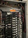
You're saying that the electrician put in 6AWG wire to the TWC. Well and good. But if you look at that cable chart, knowing that you've got a 60A circuit with a 60A breaker, you darn well had better
not be using TW or UF type wire, which can legitimately only carry 55A. You had better be using one of the other types that are rated for a higher temperature and can do 65 or 75A. A building inspector, if the electrician got that wrong, would make the electrician rip out the wire and put in the correct type. Or put in a smaller circuit breaker and re-provision the TWC.
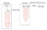
Next: The electrician put 2 AWG to an 80A breaker on the Main. Well and good. Go to the wire chart: Looks like all the types of 2AWG can handle 80A, so that's good.
Finally: Load Analysis.
There's this tricky bit: You never want to pop the breaker on the main or the breaker to the sub-panel. I happened to work in telecom before retiring. There's this thing: If everybody picks up their phones at 9 a.m. on Mother's Day, almost everybody gets a fast busy with No Circuits Available. Or no dial tone, period. That's because telephone companies don't design their networks assuming that literally everybody is talking at the same time. They look at statistics and work out percent up-time and size their networks to
that.
Electricians do the same thing. If a breaker box has fifteen 15A breakers in it, it's a gimmie that
all of those won't be drawing, say, 12A at the same time. But, say one wants to add another heavy load, be it a Tesla or a new electric oven? Then said electrician does a Load Analysis. They add up the square footage of the house (lighting), multiply it by factors, all the various loads in the house, and so on. At the end, it pops up a number, in Amps. Here's a link to one of these things:
Electrical Load Calculations for Residential Service Panel - Online Load Calculator. Note that the form has
derating, which has to do with the fact that not everything is on at the same time, or is even drawing the maximum number of amps.
So, your sub-panel is pretty much an 80A breaker system. And you've got your house hooked to it. If the maximum number of amps of
everything except the Tesla circuit, by the load analysis rating, is 20A, then, obviously, you can add an 60A breaker for the Tesla.
Note that you can take the load analysis rating for the sub-panel, put that into your main panel, work out the loads on the Main via the same form, and the total load had better be less than the 100A rating for the whole house.
The Load Analysis procedure is, no kidding, in the NEC. So electrical inspectors definitely know about this and will enforce it.
Now, while I'm an electronics engineer, I'm very much not an electrician, or even a utilities-type electrical engineer. (Although I've certainly messed with 100A+ 48V circuits before now.) I've casually looked at houses of friends and stuff, especially after getting a Tesla and becoming Aware of everything in this direction. One house I looked at, built in the 60's, had a 60A breaker panel with two single slots open. Clearly, this lady wasn't going to be able to run a 60A circuit for a Tesla!
My place just so happened to be relatively recent construction and came with a 200A panel; so adding a 60A breaker wasn't an issue. You've got a 100A panel.. so that's a-kinda close. After a load analysis, people have been known to:
- End up getting a bigger amperage drop from the power pole.
- Replace the breaker box with a bigger one.
Both are $$$. However.. depending upon where you live.. The State of New Jersey actually subsidizes both of the above (and the cost of a TWC) if doing the above is necessary so one can charge one's car. YMMV.
In any case: If a load analysis says that 60A is Too Darn Much for your place, nothing stops you from changing the breaker to, say, a 30A number and recommissioning the TWC for that number. You'll still get your car charged overnight, it'll just take a little longer.
Hope this helps.