Welcome to Tesla Motors Club
Discuss Tesla's Model S, Model 3, Model X, Model Y, Cybertruck, Roadster and More.
Register

'24 Wall Connector, NACS

This site may earn commission on affiliate links.
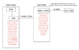
My questions are in the attached picture.

-Is there something wrong with changing the 80A breaker to the subpanel, to 100A or 125A, even though it is down stream of the 100A main breaker for the main panel so would never trip? The wire can handle it. Point being that with 80A breaker going to subpanel, I can only 80A*80%=64A. I am concerned that 64A minus 48A leaves not enough for dish washer, washer/drier, etc.

-Shouldn't the 40A breaker pop when running at 48A for 30 min? Why didn't it? What is going on? Tesla app confirmed car was receiving 48A and about 232V.

Thanks in advance!

Background: the electrician, instead of running a dedicated line from the meter to the garage since they are at opposite diagonal ends of the home, swapped the wiring from main panel to sub panel, with 2 AWG, so we could reuse the conduit there. And ran new wire and conduit only from subpanel in the garage, to the other end of the garage, so save money for me. This all sounds logical to me, but what doesn't make sense are the breaker values. I feel like they are way too conservative and waste ampacity of the wires installed. I think the 80A breaker going to the subpanel could pop unnecessarily, though my understanding is there is no safety concern since the wires are all large enough to not get hot.
 

Attachments

  • Screenshot 2024-02-01 at 11.14.12 AM.png
    Screenshot 2024-02-01 at 11.14.12 AM.png
    331.4 KB · Views: 34
100A requires 1 AWG copper wire


Provided the wire from the subpanel to the car is not #6 Romex, you can use a 60-amp breaker, #6 Romex is rated to 55-amps and is not suitable for use in a 60-amp circuit. The most likely reason the breaker has not tripper is likely because the wall connector is not set to 60-amps, which would draw 48-amps, it is probably set to a 40-amp circuit, which draws 32-amps.

As to load, the math is this: if the wall connector is set to 60-amps then it will draw 48-amps. We subtract that from 80-amps, which leaves 32-amps available. Since the rest of the load is considered to be an intermittent load, the full 32-amps is allowable for use
 
Last edited:
-Shouldn't the 40A breaker pop when running at 48A for 30 min? Why didn't it? What is going on? Tesla app confirmed car was receiving 48A and about 232V.

Missed this line, but asking Tesla is not what you need to do. Plug in the car and look at the charging screen, you should see two number with a slash in-between. If you are charging at 48-amps this should read 48/48. If it reads say 32/48 this usually means the car voltage is too low to support the higher charge rate (assuming you have not dialed down the rate in the car) and the car has downgraded charging speed (to 32-amps in this example.)
 
Last edited:
Missed this line, but asking Tesla is not what you need to do. Plug in the car and look at the charging screen, you should see two number with a slash in-between. If you are charging at 48-amps this should read 48/48. If it reads say 32/48 this usually means the car voltage is too low to support the higher charge rate (assuming you have not dialed down the rate in the car) and the car has downgraded charging speed (to 32-amps in this example.)
Oh, not sure if I was unclear.

I meant yes the Tesla app was shouding 48/48 so I was charging at 48A.
 
OK, let's take this from the bottom.

Teslas have, in them, for AC input, a maximum of three 18A AC to DC converters that charge ye battery. If you have a LR or P version of a Tesla, you'll get three of these running in parallel for a maximum current draw of 48A. If you have an SR version of a Tesla, there's but two of these converters, so the maximum current draw for one of those is 36A. (Pretty much, the number of these chargers in the car is sized to the size of the battery).

Just as a confirmation: You do see 48A @ 240VAC on the screen of the car when charging, correct? And the car is a non-SR as well, if that's the case?

Next: Again, just so we're clear: The car has No Clue, on its own, what the amperage of the circuit it's hooked to is. There's a small computer in the TWC (as well as the Tesla Mobile Connector, or a Juicebox, or whatever) that has been commissioned/provisioned to know the amperage of the circuit. Using a protocol, the car asks the TWC (or whatever) how much current it can supply. If the amount of current is more than the car can accept, the car's limit wins. If the amount of current is less than the car can accept, that lower limit wins. This is why when you go to, say, a public J1772-compatible connector in a parking lot or something it doesn't draw 48A; it draws whatever the parking lot connector says it's good for.

So, the above is why one commissions the Tesla Wall Connector. You're programming the controller in the TWC so it can tell the car what's available. The car's computer does the rest.

Next: Maybe you know this, maybe not. The National Electric Code doth state that, with a continuous heavy load, that the circuit that one is drawing current from shall be degraded by 20%. What this means: You got a 120 VAC 15A socket in the house and you plug the car into it? The car doesn't draw 15A, it draws 12A, which is 80% of the circuit rating. Why? HEAT. The wires, the insulation, the house insulation batting in the wall, and all that have thermal resistance to the outside world. Power gets dissipated in copper (or any conductor) as I*I*(Resistance of the wire); that makes the wire heat up. If it gets too hot, it degrades the insulation (or worse) and, eventually if one is just close to the limit, or a heck of a lot faster if one is over the limit, the insulation breaks down. This can and has lead to House Fires, so this rule is violated at your peril.

So, if you're planning on drawing 48A, then you need a 60A circuit (80% of 60A = 48A), with 60A wire, and a 60A breaker.

Note that one does not run a 60A (or 15A, or whatever) circuit at its rated current for more than a transient's worth of time. For one thing, a 60A breaker (say) will, nominally, after a while, of running 60A will pop open. But given manufacturing variations, it might not. Running the circuit at 48A, beyond keeping the house from catching on fire, keeps the breaker from doing nuisance blows. Besides: breakers are thermal elements, like light bulbs. When you run it close to the limit, that heats up the element, making it expand and contract as one turns the load on and off. Do enough of that and the breaker fails. If it fails open, well, that's good. If it fails short.. it's no longer doing its job and, if one really does have a short in the circuit, it's House Fires R Us.

Next: The wire between the TWC and the panel. It's supposed to be a 60A circuit. As you might expect, the NEC and various local electrical codes have a lot to say about that. Here's a link to a typical chart found on the interwebs: Wire Size Chart

If you look at that chart, right along the top, there's the ambient temperature that the wire is rated for. For the various types of wire, the lower the rated ambient temperature, the less current a given gauge of wire is rated for. And that goes right back to heat: Get the insulation too hot and it degrades. We're not talking the copper melting, here: We're talking about failing the insulation.

You're saying that the electrician put in 6AWG wire to the TWC. Well and good. But if you look at that cable chart, knowing that you've got a 60A circuit with a 60A breaker, you darn well had better not be using TW or UF type wire, which can legitimately only carry 55A. You had better be using one of the other types that are rated for a higher temperature and can do 65 or 75A. A building inspector, if the electrician got that wrong, would make the electrician rip out the wire and put in the correct type. Or put in a smaller circuit breaker and re-provision the TWC.

Next: The electrician put 2 AWG to an 80A breaker on the Main. Well and good. Go to the wire chart: Looks like all the types of 2AWG can handle 80A, so that's good.

Finally: Load Analysis.

There's this tricky bit: You never want to pop the breaker on the main or the breaker to the sub-panel. I happened to work in telecom before retiring. There's this thing: If everybody picks up their phones at 9 a.m. on Mother's Day, almost everybody gets a fast busy with No Circuits Available. Or no dial tone, period. That's because telephone companies don't design their networks assuming that literally everybody is talking at the same time. They look at statistics and work out percent up-time and size their networks to that.

Electricians do the same thing. If a breaker box has fifteen 15A breakers in it, it's a gimmie that all of those won't be drawing, say, 12A at the same time. But, say one wants to add another heavy load, be it a Tesla or a new electric oven? Then said electrician does a Load Analysis. They add up the square footage of the house (lighting), multiply it by factors, all the various loads in the house, and so on. At the end, it pops up a number, in Amps. Here's a link to one of these things: Electrical Load Calculations for Residential Service Panel - Online Load Calculator. Note that the form has derating, which has to do with the fact that not everything is on at the same time, or is even drawing the maximum number of amps.

So, your sub-panel is pretty much an 80A breaker system. And you've got your house hooked to it. If the maximum number of amps of everything except the Tesla circuit, by the load analysis rating, is 20A, then, obviously, you can add an 60A breaker for the Tesla.

Note that you can take the load analysis rating for the sub-panel, put that into your main panel, work out the loads on the Main via the same form, and the total load had better be less than the 100A rating for the whole house.

The Load Analysis procedure is, no kidding, in the NEC. So electrical inspectors definitely know about this and will enforce it.

Now, while I'm an electronics engineer, I'm very much not an electrician, or even a utilities-type electrical engineer. (Although I've certainly messed with 100A+ 48V circuits before now.) I've casually looked at houses of friends and stuff, especially after getting a Tesla and becoming Aware of everything in this direction. One house I looked at, built in the 60's, had a 60A breaker panel with two single slots open. Clearly, this lady wasn't going to be able to run a 60A circuit for a Tesla!

My place just so happened to be relatively recent construction and came with a 200A panel; so adding a 60A breaker wasn't an issue. You've got a 100A panel.. so that's a-kinda close. After a load analysis, people have been known to:
  1. End up getting a bigger amperage drop from the power pole.
  2. Replace the breaker box with a bigger one.
Both are $$$. However.. depending upon where you live.. The State of New Jersey actually subsidizes both of the above (and the cost of a TWC) if doing the above is necessary so one can charge one's car. YMMV.

In any case: If a load analysis says that 60A is Too Darn Much for your place, nothing stops you from changing the breaker to, say, a 30A number and recommissioning the TWC for that number. You'll still get your car charged overnight, it'll just take a little longer.

Hope this helps.
 
  • Like
Reactions: HankE-LA and ATPMSD
OK, let's take this from the bottom.

Teslas have, in them, for AC input, a maximum of three 18A AC to DC converters that charge ye battery. If you have a LR or P version of a Tesla, you'll get three of these running in parallel for a maximum current draw of 48A. If you have an SR version of a Tesla, there's but two of these converters, so the maximum current draw for one of those is 36A. (Pretty much, the number of these chargers in the car is sized to the size of the battery).

Just as a confirmation: You do see 48A @ 240VAC on the screen of the car when charging, correct? And the car is a non-SR as well, if that's the case?

Next: Again, just so we're clear: The car has No Clue, on its own, what the amperage of the circuit it's hooked to is. There's a small computer in the TWC (as well as the Tesla Mobile Connector, or a Juicebox, or whatever) that has been commissioned/provisioned to know the amperage of the circuit. Using a protocol, the car asks the TWC (or whatever) how much current it can supply. If the amount of current is more than the car can accept, the car's limit wins. If the amount of current is less than the car can accept, that lower limit wins. This is why when you go to, say, a public J1772-compatible connector in a parking lot or something it doesn't draw 48A; it draws whatever the parking lot connector says it's good for.

So, the above is why one commissions the Tesla Wall Connector. You're programming the controller in the TWC so it can tell the car what's available. The car's computer does the rest.

Next: Maybe you know this, maybe not. The National Electric Code doth state that, with a continuous heavy load, that the circuit that one is drawing current from shall be degraded by 20%. What this means: You got a 120 VAC 15A socket in the house and you plug the car into it? The car doesn't draw 15A, it draws 12A, which is 80% of the circuit rating. Why? HEAT. The wires, the insulation, the house insulation batting in the wall, and all that have thermal resistance to the outside world. Power gets dissipated in copper (or any conductor) as I*I*(Resistance of the wire); that makes the wire heat up. If it gets too hot, it degrades the insulation (or worse) and, eventually if one is just close to the limit, or a heck of a lot faster if one is over the limit, the insulation breaks down. This can and has lead to House Fires, so this rule is violated at your peril.

So, if you're planning on drawing 48A, then you need a 60A circuit (80% of 60A = 48A), with 60A wire, and a 60A breaker.

Note that one does not run a 60A (or 15A, or whatever) circuit at its rated current for more than a transient's worth of time. For one thing, a 60A breaker (say) will, nominally, after a while, of running 60A will pop open. But given manufacturing variations, it might not. Running the circuit at 48A, beyond keeping the house from catching on fire, keeps the breaker from doing nuisance blows. Besides: breakers are thermal elements, like light bulbs. When you run it close to the limit, that heats up the element, making it expand and contract as one turns the load on and off. Do enough of that and the breaker fails. If it fails open, well, that's good. If it fails short.. it's no longer doing its job and, if one really does have a short in the circuit, it's House Fires R Us.

Next: The wire between the TWC and the panel. It's supposed to be a 60A circuit. As you might expect, the NEC and various local electrical codes have a lot to say about that. Here's a link to a typical chart found on the interwebs: Wire Size Chart

If you look at that chart, right along the top, there's the ambient temperature that the wire is rated for. For the various types of wire, the lower the rated ambient temperature, the less current a given gauge of wire is rated for. And that goes right back to heat: Get the insulation too hot and it degrades. We're not talking the copper melting, here: We're talking about failing the insulation.

You're saying that the electrician put in 6AWG wire to the TWC. Well and good. But if you look at that cable chart, knowing that you've got a 60A circuit with a 60A breaker, you darn well had better not be using TW or UF type wire, which can legitimately only carry 55A. You had better be using one of the other types that are rated for a higher temperature and can do 65 or 75A. A building inspector, if the electrician got that wrong, would make the electrician rip out the wire and put in the correct type. Or put in a smaller circuit breaker and re-provision the TWC.

Next: The electrician put 2 AWG to an 80A breaker on the Main. Well and good. Go to the wire chart: Looks like all the types of 2AWG can handle 80A, so that's good.

Finally: Load Analysis.

There's this tricky bit: You never want to pop the breaker on the main or the breaker to the sub-panel. I happened to work in telecom before retiring. There's this thing: If everybody picks up their phones at 9 a.m. on Mother's Day, almost everybody gets a fast busy with No Circuits Available. Or no dial tone, period. That's because telephone companies don't design their networks assuming that literally everybody is talking at the same time. They look at statistics and work out percent up-time and size their networks to that.

Electricians do the same thing. If a breaker box has fifteen 15A breakers in it, it's a gimmie that all of those won't be drawing, say, 12A at the same time. But, say one wants to add another heavy load, be it a Tesla or a new electric oven? Then said electrician does a Load Analysis. They add up the square footage of the house (lighting), multiply it by factors, all the various loads in the house, and so on. At the end, it pops up a number, in Amps. Here's a link to one of these things: Electrical Load Calculations for Residential Service Panel - Online Load Calculator. Note that the form has derating, which has to do with the fact that not everything is on at the same time, or is even drawing the maximum number of amps.

So, your sub-panel is pretty much an 80A breaker system. And you've got your house hooked to it. If the maximum number of amps of everything except the Tesla circuit, by the load analysis rating, is 20A, then, obviously, you can add an 60A breaker for the Tesla.

Note that you can take the load analysis rating for the sub-panel, put that into your main panel, work out the loads on the Main via the same form, and the total load had better be less than the 100A rating for the whole house.

The Load Analysis procedure is, no kidding, in the NEC. So electrical inspectors definitely know about this and will enforce it.

Now, while I'm an electronics engineer, I'm very much not an electrician, or even a utilities-type electrical engineer. (Although I've certainly messed with 100A+ 48V circuits before now.) I've casually looked at houses of friends and stuff, especially after getting a Tesla and becoming Aware of everything in this direction. One house I looked at, built in the 60's, had a 60A breaker panel with two single slots open. Clearly, this lady wasn't going to be able to run a 60A circuit for a Tesla!

My place just so happened to be relatively recent construction and came with a 200A panel; so adding a 60A breaker wasn't an issue. You've got a 100A panel.. so that's a-kinda close. After a load analysis, people have been known to:
  1. End up getting a bigger amperage drop from the power pole.
  2. Replace the breaker box with a bigger one.
Both are $$$. However.. depending upon where you live.. The State of New Jersey actually subsidizes both of the above (and the cost of a TWC) if doing the above is necessary so one can charge one's car. YMMV.

In any case: If a load analysis says that 60A is Too Darn Much for your place, nothing stops you from changing the breaker to, say, a 30A number and recommissioning the TWC for that number. You'll still get your car charged overnight, it'll just take a little longer.

Hope this helps.
Thanks so much for the information!

To answer your question: Yes, I saw 48/48A, 232V (from voltage drop of the length, I assume that is 240V at the meter). It is a model 3 performance.

I don't have an electric stove. Another company calculated that 48A charging is ok for 100A, but they were assuming the car charge line was running directly from the main panel (100A breaker) to the charger. That is different from the 80A breaker at the subpanel. I am concerned that 80A breaker (64A actual) is not enough for 48A charging (60A breaker), since that leaves 16A left over for washer/drier, dish washer, etc. to run off of.

I live in California.

*Edited to 48A.
 
Last edited:
Thanks so much for the information!

To answer your question: Yes, I saw 40/40A, 232V (from voltage drop of the length, I assume that is 240V at the meter). It is a model 3 performance.

I don't have an electric stove. Another company calculated that 48A charging is ok for 100A, but they were assuming the car charge line was running directly from the main panel (100A breaker) to the charger. That is different from the 80A breaker at the subpanel. I am concerned that 80A breaker (64A actual) is not enough for 48A charging (60A breaker), since that leaves 16A left over for washer/drier, dish washer, etc. to run off of.

I live in California.
Um. So, let's do a quick double-check: You saw 40/40A? Not 48A/48A?

If you saw 40/40, the implication is that the TWC has been provisioned to think that it's on a 50A circuit. 80% of 50A = 40A, and there you are. Who did the provisioning? If you just made a (slight) error, and it's 48/48, then the TWC is provisioned for a 60A circuit.

Next: I agree with you about that 80A sub-panel looking a bit on the scant side. I'd suggest going to that Electrical Load Calculations for Residential Service Panel - Online Load Calculator and start filling out terms. As I said, I'm not an electrician, but I know some things. In no particular order:
  • The "small appliance" line is about things like microwaves, garbage disposals, refrigerators, and gas (not electric) stoves. By code, each of those is on its own circuit. But I suppose you can throw in coffee makers and other such that you use often.
  • Note that "1500VA" means 1500 Watts. With a 120 VAC circuit, that's about 12A.
  • In the various steps, where they mention things like a HVAC or whatever, it's on you to find the metal label on the equipment and get the power numbers off of it. You may end up pulling the laundry washing machine away from the wall to get a look at the back.. or find the manual, where that info ought also to be.
I've never actually done one of these forms, but it seems straight forward.

Hm. If you can find the crowd that did the check on your "48A is OK" bit, get a look at their form, and see what it says with respect to an 80A breaker. Or pay them $50 or something to find out if that 80A breaker is enough.
 
Of course I had to make a typo while correcting.

Sorry, I saw 48/48A, not 40/40A!!

I saw 48A and i was surprised the 40A breaker did NOT break. I'm thinking it is a bad breaker.
Yeah.. about that 40A breaker. That bothers me quite a bit.

As it happens, I've periodically had the job of sizing fuses/breakers in the presence of surges and such. There's an actual science involved and interesting graphs called 'i^2-t' curves that handle fast-blow and slow-blow fuses. Let me put one up here..

1706824226230.png

The above is from Littlefuse's Technology Handbook.

So, time on the vertical axis; current on the horizontal; and it's a log-log scale. Look at the curve for a 1A fuse (in this case). As time goes longer than 100s, the curve gets more and more vertical - but, as it leaves the plot, it's leaving it at 2A, not 1A!

Reason is: The nominal blowing current for a 1A fuse is 1A, but it's probably a 10% fuse, so it could be at 0.9 to 1.1A. Further, it might take minutes for it to finally blow. Or longer.

And that 10% number is real. When one designs, the right thing to do is to broaden one of those curves with a pair of curves, to each side, with one on the left of the desired curve at 90% of the rating and one to the right at 110% of the desired rating.

Real breakers are like very slow-blow fuses and the spec sheets often don't have the curves; just three or so numbers that denote some guaranteed-to-blow times, or guaranteed not-to-blow times.

So.. I think it's odd that the 40A breaker didn't pop, but not completely out of the question.

When it gets down to it, the specs on breakers or fuses is if the current is, say, 5X the current rating, then there's a number that says the circuit will open up in "yea" many milliseconds.

The whole point of fuses/breakers is to Save The Day with a massive overcurrent present, preferably before the wires in the walls get so hot that the insulation breaks down. I would'a thought that 48A on a 40A breaker woulda popped, too, but if one squints.. maybe it wasn't that much of an overcurrent. In that one case. Wouldn't do it on a regular basis, though: House fires.
 
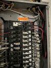
I will go back and try to verify as much information about the wire when I get a chance. All I know right now, is the electrician told me it is 6 AWG wire.

Picture of the wire in case anyone can tell by looking at it, it is the pair of bigger red and black wires.
 

Attachments

  • IMG_1191.jpg
    IMG_1191.jpg
    576.5 KB · Views: 17
I"m trying to figure out if:
1. is it safe to charge at 48A or do I need to get someone to make small changes to charge safely at 48A?
2. If not safe, can I turn it down to 40A at the charger as well as get breakers swapped for 40A (so 50A breaker).

It isn't totally clear to me.
 
Sorry, I saw 48/48A, not 40/40A!!

I saw 48A and i was surprised the 40A breaker did NOT break. I'm thinking it is a bad breaker.

I agree, something is very wrong, you should stop using it! A new breaker should be only about $15-20 so…

If the wire is 6 AWG and is not Romex, replace it with a 60-amp breaker otherwise, get a 50-amp breaker and set the wall connector to a 50-amp circuit. This will give you a charging rate of 40-amps.
 
I saw 48A and i was surprised the 40A breaker did NOT break. I'm thinking it is a bad breaker.

I've never seen a circuit breaker fail in way that caused it to trip at a higher current.

Every circuit breaker failure I've ever seen either wouldn't reset or would trip at a lower current.

With that said, let's look at the trip curve for a Square D QO series circuit breaker. These have been around for decades and are very common. Other breakers are similar.

As you can see, the 40A breaker may never trip until its current rating has been exceeded by 135% (which would be 54A) or it may trip in as little as about 250 seconds at 48A (this will vary due to tolerances - the chart shows a minimum and maximum) or it may never trip (the chart tops out at 10,000 seconds which is about 2 hours, 45 minutes).

135% of 40 is 54, so I'm not surprised that a 40-amp breaker didn't trip at 48 amps.

1706826053465.png
 
I"m trying to figure out if:
1. is it safe to charge at 48A or do I need to get someone to make small changes to charge safely at 48A?
2. If not safe, can I turn it down to 40A at the charger as well as get breakers swapped for 40A (so 50A breaker).

It isn't totally clear to me.
First, and I'm dead serious here, and I Am Not Kidding: Stop charging at 48A. Period. Now. You care about your wife and kiddies? Running 48A through a 40A breaker is one step closer to a house fire. Do Not Do That Thing.

Second: The simplest thing right now is to re-commission your Tesla Wall Connector. I happen to have a first generation Wall Connector. There's no web interface. One takes the cover off, turns off the breaker, and there's a couple of rotary switches. In the manual, it says what the rotary switches have to be set to for various amperages. Mine is set to the position for a 60A circuit, 48A load. You need to figure out how to get into that web interface and tell the TWC that it's on a 40A circuit with a 32A load.

GO DO THIS RIGHT NOW!!!

You could, perhaps, set the charging current for your car at a maximum of 32A. But I wouldn't take the risk.
 
  • Like
Reactions: ATPMSD
Don't worry. Not charging on it now. I also know how to recommission to lower current as well.

the 40A breaker has been swapped for 60A breaker by the electrician.


I am still wondering if the wiring is sufficient for 48A actual (60A breaker), or 40A actual (50 A breaker).

I am going to recommission to 40A charging 50A breaker now to be safe while I figure out the wiring.

Just so I understand, if the wiring were to be correctly sized and correct type of insulation, for 60A breaker, 48A charging, but there was a 40A breaker is that unsafe?

I thought it isn't unsafe, it will just start to prematurely trip? (nuisance trip)

Or is the safety concern that the 40A breaker did not trip at 48A?
OK. That picture showed a 40A breaker. @zroger73 pointed out, above, that, following the specs on a 40A breaker, it might not trip for currents under 56A. I guessed that, he showed it.

You can very definitely run 48A on a 60A breaker.

If the electrician used 6AWG wire to the TWC with the right type of insulation then it should be fine on a 60A circuit. Hm. If you look, carefully, at that wire in there, you may see lettering that identifies what type of wire it is. The lettering often includes the temperature rating. If it says 60C or 140F, it's 55A wire; if it's higher than that, then it's good for 65 or 75A and you're ok on that front.

As to whether you can run a 60A circuit on an 80A sub panel with the rest of the house also present: That's the load analysis part. I think you want that done, period, no matter what else you're doing. Better to nail it down than guess.

And.. One major part of my work before I retired was analyzing field failures of telecom gear. A memorable number of systems got returned with holes blown throw them, no kidding, usually from lightning strike/grounding issues, but other problems as well. So, let's just say I've got wavy antennas when it comes to Stuff Failing, be it integrated circuits, fuses, resistors, capacitors, FETs, and all sorts of other kinds of stuff. (A good hunk of my job was, after figuring out what died, was making sure that whatever happened, it Never Happened Again.)

Thing is: Most breakers run a bit of current through an element that expands when it gets hot and contracts when it gets cold. If it gets hot enough, then the breaker mechanically pops and opens up. Just like the thermostat in a house.

Power dissipated in an element like this goes as I*I*(Resistance of the element). Notice the I^2 factor. So, say one has a 60A breaker running at 60A and the same breaker running at 48A. The amount of power dissipated in the breaker goes as (48*48)/(60*60) = 0.64 times less; which means that it expands 0.64 less than what would be nominally required to pop said breaker. Makes sense: NEC says to run at 80%, or 0.8, and 0.64 is 0.8^2.

But every time one starts charging, then stops charging, that bit of metal is going to flex back and forth. Flex it back and forth a lot and, well, just like flexing a paperclip wire back and forth: The sucker's going to break, physically.

This is why, in general, breakers don't last forever. But running a breaker closer to its limit than the NEC calls for, and manufacturers expect you to, well, that way lies shortened life times and Trouble.

Problem is: You ask me: What happens if that bit of metal breaks? Um. Dunno. But, in general, things like this, when they break and the bits of metal fly all over, will either break in a way that the breaker opens up, in which case one doesn't get charging or whatever, but that's safe, or it fails closed, in which case.. come the day when there is a short, the house burns down.

A breaker is a save-the-day piece of gear. It's not to be trifled with by going for nuisance blows. Frankly, don't risk your life.
 
  • Like
Reactions: zroger73