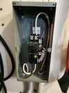
Looking at that subpanel picture, it is fair to say your electrician's competence is questionable. There are so many things wrong at first glance:
1) Using a GFCI breaker, as already discussed. A GFCI breaker should not feed an internally GFCI-protected device (the wall charger), just ups the odds of nuisance trips. Your electrician does not read installation manuals?
2) A GFCI on a 2 wire load circuit MUST include the neutral wire from the line side, per manufacturer documentation. So the feed wire should have been 2 hots, a neutral and a ground, not 2 hots and a ground. That is improperly wired and should be replaced with a standard (non-GFCI) breaker. See
https://download.schneider-electric...nstruction+sheet&p_File_Name=48840-435-03.pdf for 2-pole GFCI wiring details.
3) The connection of the GFCI pigtail looks like it was done by a 3 year old. Very poor quality.
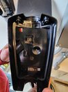
4) Running NM-B (Romex) inside conduit is poor practice. Simple individual THHN wires is the proper way to run wire inside conduit.
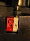
5) Your electrician should have advised you not to use that breaker as a switch to 'save money'.
6) Your wire looks potentially undersized. Looks like 6/2 or possibly 8/2 NM-B 'Romex', so there is a possibility your breaker is oversized for the wire. Hard to tell from the picture, but bears further scrutiny given the other errors here. Proper breaker & wire sizing is a significant safety issue.
7) The hot wires in and out of your breaker must not be white wires. White means that wire is a grounded conductor, which yours most certainly is not. The electrician should have used a sharpie to color them black or wrapped with black electrical tape. This is a very basic mistake and speaks highly to just how poor your electrician is.
Are you sure your electrician is licensed? So much is wrong or suspect here. This would have never passed an inspection. I suggest you never hire that electrician to touch another inch of your wiring in the future. This is a glaring example why installations should be permitted and inspected, even when done by 'professionals'.