


Caution: Wall of text ahead!
So, I got a secondhand Gen3 HPWC (TPN:1457768-01-F) that had known issues at full power and of course ran it right up to 48 amps to see what she'd do(note it had updated firmware). For a little while it did 48 amps, but after a half hour in my 20f garage, it throttled back to 38-42 amps and stayed oscillating around there for a few hours until I turned it off when the outside of the case just above the identification plate reached 120f(still in my 20f garage!) Seeing a chance for a little electronic adventure, I opened it up to see what made it tick.
First, we have the familiar front. It is removed by removing two screws from the backside near the bottom, and then carefully sliding the glass downwards maybe a half inch.
Next picture is the backside, where the teeny screws(for the front) are seen at the bottom, the ground connector is the lower one, and L1/L2 are the upper ones. The circle near the middle is an optical temperature sensor, watching for the input lugs to overheat.
After the decorative glass is removed, we see eight screws holding a clear plastic plate(five were already removed in the picture!). It is gasketed and fairly weathertight, which is why there are eight screws. Remove them and the clear plastic comes off easily.
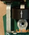
Now note the three connections at the bottom for the power and ground lines going out the cable to the handle. On mine, the screws for the power lines weren't as tight as I'd expect. Also note the small bundle of wires that clips into a black socket halfway up, they are signaling wires and a temperature sensor for the handle, and undoubtedly the button in the handle as well. Finally, note the wifi wire at the top. Be careful about pulling that off, in that it pops off perpendicular to the board, it doesn't slide off like a spade lug.
So here's where the overheating bits come into play... it gets ugly fast...
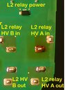
Those two big dark brown things are each two-pole relays, one relay for L2, and the other relay for L1. Tesla's hope seems to be that the two poles(called A and B in the pictures, in small blue font) of each of the two relays will take 24 of the 48 amps of that 120V leg. That hope is more of a dream, but I was surprised by how it happened. The incoming L2(I did all my analysis on L2 because it was closer to the edge of the board) spade is split into two smaller 'bars' that have a cross-sectional area between 9 and 10 AWG. I don't know exactly what the material is, but its nonferrous, I'm guessing tin coated copper or the like. I'm really surprised at this, since it'd be running 'hot'ish even with a perfect 24 amp distribution. Notably, the longer of the legs is around 4" long, the shorter is probably around 2.75" long. Right there, there's an imbalance that might throw things off, especially running the conductor at such a high current.
I removed the board from the case and was somewhat shocked(pun intended) that the PCB board was getting scorched on one of the two input poles on each of the relays. The immediate suspicion was that that pole was for some reason taking more than the desired 24 amps. The surprising bit is that for the left relay(L2), the pole connected to the LONGER input bar was the one that was discoloring, even though it should have higher resistance and therefore be carrying slightly less current.
Also note on the back of the board the optical temperature sensor, constantly looking at the input wires(from the house) to see if they are overheating due to being too small or not tightly attached. Luckily(or not), they also are checking the heat of the rest of the HPWC, even if only indirectly. This is a good thing, since it saves the entire HPWC from becoming a flaming decoration on your garage wall.
So, after some deliberation, I soldered five test leads to the underside of the board and reassembled it. The five leads were:
Arrival of L2 bus bar on the circuit board for pole A
Departure of L2 pole A relay connection(like a quarter inch of PCB board away!)
Arrival of L2 bus bar on the circuit board for pole B
Departure of L2 pole B relay connection(like 3/8 inch of PCB board away!)
Return of L2 pole A from relay.
With all these connections(and the metal bars that are relatively easily accessible from the front) and a fairly precise multimeter, I can see pretty clearly what the losses are along the way, although there's a decent chance my signals are a little polluted by the electric field of the relays. It turns out that the A pole of the L2 relay is taking around 44(!) amps of the 48 I'm charging with, and this is causing just stupid levels of heating in the box even though its not really all THAT much power being dissipated. I see around 0.21V AC is lost from the input metal bar to the output lug of the L2 side, which means that its dumping around 10 watts(0.21*48)(. Sadly, those watts have nowhere but heat to go, in a small brown package and the metal bus bar going into it.
I didn't have detailed measurements on the second(L1) relay, but saw it was dropping even MORE voltage, like 0.285V.
As an idea of temperatures in this region, the space between the two relays was reading at 250f. The relays themselves were 200f in spots, after an hour or so of running with all the covers OFF. On the bright side, it kept charging at 48 amps for around four hours, with no throttling at all.
Some might notice the rogoski coils on three of the four output lines from the relays. I assume that the software doesn't actively read them, or I'd hope something would actively shut down the system when it sees one pole of each relay is running 91% of the current. This HPWC shouldn't have been allowed out of the factory the way it is, IMHO. I also assume that the reason there are only three coils is that the HPWC could(if it cared to) see the current leaving on L1(cores 2 and 3) and assume its coming back in the same amount on L2(core not-there and 1), and thereby know the unknown not-there current individually.
So, the reason for the mismatch:
At such high current levels, even the negligible resistance of wires and relays becomes significant. Initially, I expected the longer bus bar(A) to be the issue, since longer means more resistance. Two identical resistances in parallel will cause half the current to flow each resistor, and the apparent resistance of the pair will be half each individual resistance. When one of the resistances is higher(like when a bus bar is longer) it should cause an increase in current to the lower resistance path, but clearly the longer bus bar is actually taking much MORE current than it should. This leads me to believe that either the other pole has excess resistance in the relay contacts themselves, or the very small bits of PCB board involved are just too resistant and inconsistent from one pole to the other. There may be something to this, since the PCB traces are TINY compared to AWG 9/10, and the PCB distance for the not-lots-of-current pole is somewhat longer, and the 'landing pad' for solder around the metal connection bars seems a bit small.. If I believe the 44/4 amp split of current, the itty-bitty chunk of PCB for the B side of L2 is showing about four times the resistance of the A side. It is unclear why they didn't link the A and B poles to each other at both the input and output sides for each relay, which would reduce the effect of the not-same-length feed bars. Maybe they were concerned about heating and cooling cycles cracking the PCB in between the poles.
IMHO, the design is flawed because it relies too heavily on balanced currents with nothing to really balance them, and it seems that even though there's enough electronics to monitor the imbalance, the logic doesn't seem to do much with that information. As a result, while its great to have redundancy, both paths through each relay should have been designed to be able to handle the full 48 amp load continuously without overheating.
I hope you have enjoyed this trip down Gen3 lane... and yes, it still works, but I won't be running it past 32 amps until I improve the B side connections.


So, I got a secondhand Gen3 HPWC (TPN:1457768-01-F) that had known issues at full power and of course ran it right up to 48 amps to see what she'd do(note it had updated firmware). For a little while it did 48 amps, but after a half hour in my 20f garage, it throttled back to 38-42 amps and stayed oscillating around there for a few hours until I turned it off when the outside of the case just above the identification plate reached 120f(still in my 20f garage!) Seeing a chance for a little electronic adventure, I opened it up to see what made it tick.
First, we have the familiar front. It is removed by removing two screws from the backside near the bottom, and then carefully sliding the glass downwards maybe a half inch.
Next picture is the backside, where the teeny screws(for the front) are seen at the bottom, the ground connector is the lower one, and L1/L2 are the upper ones. The circle near the middle is an optical temperature sensor, watching for the input lugs to overheat.
After the decorative glass is removed, we see eight screws holding a clear plastic plate(five were already removed in the picture!). It is gasketed and fairly weathertight, which is why there are eight screws. Remove them and the clear plastic comes off easily.
Now note the three connections at the bottom for the power and ground lines going out the cable to the handle. On mine, the screws for the power lines weren't as tight as I'd expect. Also note the small bundle of wires that clips into a black socket halfway up, they are signaling wires and a temperature sensor for the handle, and undoubtedly the button in the handle as well. Finally, note the wifi wire at the top. Be careful about pulling that off, in that it pops off perpendicular to the board, it doesn't slide off like a spade lug.
So here's where the overheating bits come into play... it gets ugly fast...
Those two big dark brown things are each two-pole relays, one relay for L2, and the other relay for L1. Tesla's hope seems to be that the two poles(called A and B in the pictures, in small blue font) of each of the two relays will take 24 of the 48 amps of that 120V leg. That hope is more of a dream, but I was surprised by how it happened. The incoming L2(I did all my analysis on L2 because it was closer to the edge of the board) spade is split into two smaller 'bars' that have a cross-sectional area between 9 and 10 AWG. I don't know exactly what the material is, but its nonferrous, I'm guessing tin coated copper or the like. I'm really surprised at this, since it'd be running 'hot'ish even with a perfect 24 amp distribution. Notably, the longer of the legs is around 4" long, the shorter is probably around 2.75" long. Right there, there's an imbalance that might throw things off, especially running the conductor at such a high current.
I removed the board from the case and was somewhat shocked(pun intended) that the PCB board was getting scorched on one of the two input poles on each of the relays. The immediate suspicion was that that pole was for some reason taking more than the desired 24 amps. The surprising bit is that for the left relay(L2), the pole connected to the LONGER input bar was the one that was discoloring, even though it should have higher resistance and therefore be carrying slightly less current.
Also note on the back of the board the optical temperature sensor, constantly looking at the input wires(from the house) to see if they are overheating due to being too small or not tightly attached. Luckily(or not), they also are checking the heat of the rest of the HPWC, even if only indirectly. This is a good thing, since it saves the entire HPWC from becoming a flaming decoration on your garage wall.
So, after some deliberation, I soldered five test leads to the underside of the board and reassembled it. The five leads were:
Arrival of L2 bus bar on the circuit board for pole A
Departure of L2 pole A relay connection(like a quarter inch of PCB board away!)
Arrival of L2 bus bar on the circuit board for pole B
Departure of L2 pole B relay connection(like 3/8 inch of PCB board away!)
Return of L2 pole A from relay.
With all these connections(and the metal bars that are relatively easily accessible from the front) and a fairly precise multimeter, I can see pretty clearly what the losses are along the way, although there's a decent chance my signals are a little polluted by the electric field of the relays. It turns out that the A pole of the L2 relay is taking around 44(!) amps of the 48 I'm charging with, and this is causing just stupid levels of heating in the box even though its not really all THAT much power being dissipated. I see around 0.21V AC is lost from the input metal bar to the output lug of the L2 side, which means that its dumping around 10 watts(0.21*48)(. Sadly, those watts have nowhere but heat to go, in a small brown package and the metal bus bar going into it.
I didn't have detailed measurements on the second(L1) relay, but saw it was dropping even MORE voltage, like 0.285V.
As an idea of temperatures in this region, the space between the two relays was reading at 250f. The relays themselves were 200f in spots, after an hour or so of running with all the covers OFF. On the bright side, it kept charging at 48 amps for around four hours, with no throttling at all.
Some might notice the rogoski coils on three of the four output lines from the relays. I assume that the software doesn't actively read them, or I'd hope something would actively shut down the system when it sees one pole of each relay is running 91% of the current. This HPWC shouldn't have been allowed out of the factory the way it is, IMHO. I also assume that the reason there are only three coils is that the HPWC could(if it cared to) see the current leaving on L1(cores 2 and 3) and assume its coming back in the same amount on L2(core not-there and 1), and thereby know the unknown not-there current individually.
So, the reason for the mismatch:
At such high current levels, even the negligible resistance of wires and relays becomes significant. Initially, I expected the longer bus bar(A) to be the issue, since longer means more resistance. Two identical resistances in parallel will cause half the current to flow each resistor, and the apparent resistance of the pair will be half each individual resistance. When one of the resistances is higher(like when a bus bar is longer) it should cause an increase in current to the lower resistance path, but clearly the longer bus bar is actually taking much MORE current than it should. This leads me to believe that either the other pole has excess resistance in the relay contacts themselves, or the very small bits of PCB board involved are just too resistant and inconsistent from one pole to the other. There may be something to this, since the PCB traces are TINY compared to AWG 9/10, and the PCB distance for the not-lots-of-current pole is somewhat longer, and the 'landing pad' for solder around the metal connection bars seems a bit small.. If I believe the 44/4 amp split of current, the itty-bitty chunk of PCB for the B side of L2 is showing about four times the resistance of the A side. It is unclear why they didn't link the A and B poles to each other at both the input and output sides for each relay, which would reduce the effect of the not-same-length feed bars. Maybe they were concerned about heating and cooling cycles cracking the PCB in between the poles.
IMHO, the design is flawed because it relies too heavily on balanced currents with nothing to really balance them, and it seems that even though there's enough electronics to monitor the imbalance, the logic doesn't seem to do much with that information. As a result, while its great to have redundancy, both paths through each relay should have been designed to be able to handle the full 48 amp load continuously without overheating.
I hope you have enjoyed this trip down Gen3 lane... and yes, it still works, but I won't be running it past 32 amps until I improve the B side connections.
Last edited by a moderator:

 Bad relay or bad connection (cold solder)
  .
.