Welcome to Tesla Motors Club
Discuss Tesla's Model S, Model 3, Model X, Model Y, Cybertruck, Roadster and More.
Register

Installing 750W 120V inverter in cabin, what's the best wiring routing? (2023)

This site may earn commission on affiliate links.
This requires theoretical max of 63A current, reading so far I'm pretty sure nothing inside available to tap into in the cabin supports this. So direct line from the LV battery is required, right?

EDIT: Or is it feasible to tap directly to the HV->LV converter terminals under the rear seat? I don't need this always on, just while the car is active.

I haven't worked with the new LFP battery yet, tips or anything to watch on this? I'm assuming an inverter will be fine handling a 15V-16V input rather than the 13.3V from the old systems.

Also I have no experience with the new heat pump configuration front end, all my prior tinkering has been with my 2018 M3. What's the best way to run a line through the "firewall", now?

Thanks in advance for any advice, information, random thoughts, scolding about doing a proper search of archives first, etc. :p

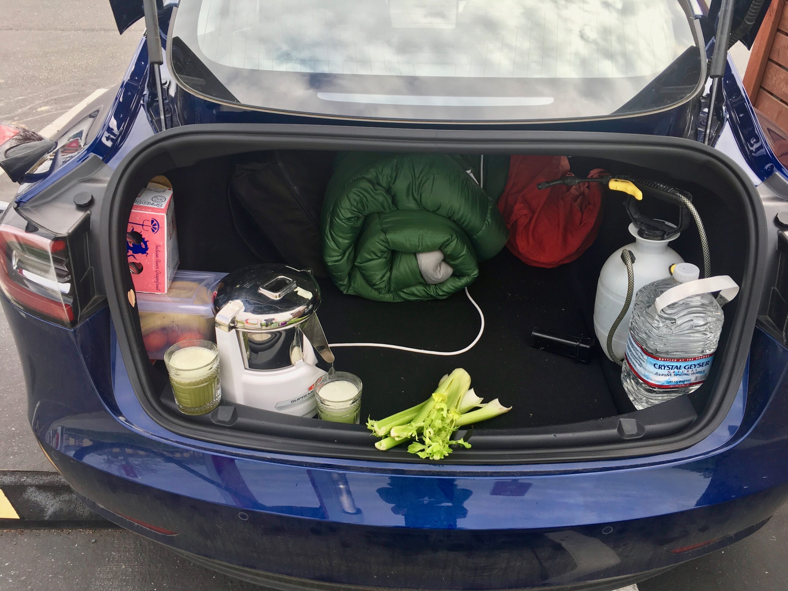
P.S. I'm pretty sure I want the inverter inside the cabin. Any heating concerns about it being overridden by concerns about shorting due to moisture if mounted outside, as well as heat dissipation issues because it looks largely packed tight AF up in there now.
 
Last edited:
The 12V battery (Acid or Li-Ion) will not have such capacity.
You could not directly tap the DC/DC inverter, it would not have enough power.
Also Tesla monitor any DC line using several circuit breakers since there is no fuse.
Any abnormal power consumption will be detected and sutdown will occur.
You will have to wait sometime for the circuit breaker to get reset.

What I would recommend is to use a separate 12V battery
that could be charged by the internal DC/DC inverter.
And use this secondary battery as power source.
You will need to have a switch mechanism to isolate the battery
from the load when the secondary battery get charged.
This isn’t accurate.

I regularly run this inverter straight off my 2018 Model 3 battery terminals, using alligator clip leads.

I’m just looking to do it in the cabin, without the hood up, on the Y
 
Last edited:
This requires theoretical max of 63A current

750W / 120V = 6.3 amps, not 63 amps

I regularly run this inverter straight off my 2018 Model 3 battery terminals, using alligator clip leads

Never connect anything directly to the Tesla 12V battery. Just because you can does not mean it is OK. The Tesla 12V battery is a tiny battery; pulling loads off it can damage the battery and messes with the car’s BMS.
 
750W / 120V = 6.3 amps, not 63 amps


Never connect anything directly to the Tesla 12V battery. Just because you can does not mean it is OK. The Tesla 12V battery is a tiny battery; pulling loads off it can damage the battery and messes with the car’s BMS.
My math was correct, 12V current is the relavent A.

Model 3 factory battery is spec’d 1000A cold crank (10s burst), 225A continuous
 
The issue is not the battery but the charging circuit feeding that battery. That's going to be what's under load during normal driving, not the battery itself.
???

The converter will limit itself to protect itself. Unless it’s the most epically badly design converter since…hell I don’t know. The 12V battery will back fill, if need be.

That’s the core of why I didn’t want to connect directly to the converter. I’m not confident that the VC_Front board will feed current backwards like that, to avoid V sag.

It’s not like the 750W inverter will run flat out all the time, that nameplate amount is just peak. Expect to run it around 300-400W, maybe. Sizing is to make sure it’ll work for motors, for starting, etc. Plus ensure it won’t run anywhere near edge of heat envelope
 
Last edited:
???

The converter will limit itself to protect itself. Unless it’s the most epically badly design converter since…hell I don’t know. The 12V battery will back fill, if need be.

That’s the core of why I didn’t want to connect directly to the converter. I’m not confident that the VC_Front board will feed current backwards like that, to avoid V sag.

It’s not like the 750W inverter will run flat out all the time, that nameplate amount is just peak. Expect to run it around 300-400W, maybe. Sizing is to make sure it’ll work for motors, for starting, etc. Plus ensure it won’t run anywhere near edge of heat envelope

Triggering a max limit is an exceptional condition for any electrical device. It's a situation to be avoided. When the DC/DC converter is operating, the 12V battery is a load, not a source. It cannot "back fill". The 12V's only function is to provide power when the converter is not working. But anyway, here's something I found which may be helpful to you:


As an electrical engineer, this is not something I would do. But that's just me and my credentials are only being listed here as a shortcut to indicate that I have some above-average understanding of electronics and electrical systems. I could be wrong.
 
  • Helpful
Reactions: ATPMSD
That’s double what I’m aiming for, that’s why I’ve not been tripping faults. Even fully live, rolling around (so steering, etc, although not running video games/theater).

Small wonder he was seeing issues, my Bolt won’t handle that sustained either (again, when draw is above DC-DC supply, V drops enough that battery back fills) So yeah, no worries. I’m not exceeding the tolerances. Not planning to run a rice cooker or a 1000W microwave or such. 😂

Converter periodically boosting the battery, as needed.

So no worries, now I just need the path for the wires. Any suggestions?

PS Or I could jump through the hoops to build out the circuit he’s talking about, but since I’m not putting that demand on it no problem. He was overloading VC_Front path.

Although in any event I probably should power off the inverter during software updates, since there’s extraordinarily activity happening then. I’ll probably have this off most of the time anyway, this was my plan & expectation. Just needed for passenger doing work or the wine bottle chiller.
 
Last edited:
now I just need the path for the wires. Any suggestions?

There is a big hole in the firewall on the right side, which is designed to pass the steering wheel in the case of Right Hand Drive cars.

MY Firewall .jpg
 
Last edited:
  • Like
Reactions: SilverStar