Hey everyone first time posting and after reading countless threads I have finally decided to take the plunge. I am looking to install 2 power walls and pre wire for a 3rd unit during this project, as well as leave room for solar in the future. I am starting off with an Eaton MBED3042B200 meter main w/ 225 amp bus 200 amp service disconnect. Not sure if it is technically allowed based off of NEC regulations but my first thoughts are to route the wires from the load side of the main service disconnect to the PW Gateway and then back from Gateway to the distribution panel. The second leg of the gateway I would plan to setup a generation sub panel to support the Powerwall and future solar install of 7.6kW. Is this even possible with the style of all in one, or will I be forced to run a sub panel for critical loads?


Welcome to Tesla Motors Club
Discuss Tesla's Model S, Model 3, Model X, Model Y, Cybertruck, Roadster and More.
Register
Install the app
How to install the app on iOS
You can install our site as a web app on your iOS device by utilizing the Add to Home Screen feature in Safari. Please see this thread for more details on this.
Note: This feature may not be available in some browsers.
-
Want to remove ads? Register an account and login to see fewer ads, and become a Supporting Member to remove almost all ads.
You are using an out of date browser. It may not display this or other websites correctly.
You should upgrade or use an alternative browser.
You should upgrade or use an alternative browser.
Powerwall Install Design
- Thread starter Bpaston
- Start date
RoBoRaT
PoPeYeD'SaiLoRDuDe
I am not at all savvy or knowleageable in anything electrical....just want to share/discuss ideas.
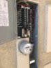
Your Main Panel is just like mine 225 BUS with 200A breaker...even your meter looks like from Southern Ca Edison.
Tomorrow is the starts our install of 10.7 kW solar system and 2 Powerwalls, taking advantage of the SGIP incentive (step 4 with SCE) plus 30% income tax credit for both solar and PW.
I wanted to have 12 kW solar but SCE and 120% calculations limited ours to 10.7 kW with 2 PW.
Are you not getting SGIP, assuming you are in SCE territory? Wouldn't it be better if you install solar with PW now, or start with solar first, than retrofit the PW system with solar later?
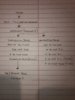
I am in SCE territory I live out in Menifee and these panels seem to be the norm out here on new construction. Long story short is I am planning to do everything but the PWs on my own and in phases since it will take some time. The first step would be figuring out the wiring and setup so that I can be ready for solar and bring in Baker to do the PWs. Once powerwalls are in I will then move to solar install. So it is really one large project that I am just trying to split up into phases if you will. Below is my dinner table line diagram and first shot of trying to plan this all out. Where I am getting hung up right now is trying to understand whether or not I would have to take into account the generation back feed on the main panel, or would it not count since I would be making use of a generation panel.
Attachments

RoBoRaT
PoPeYeD'SaiLoRDuDe
OK, I see, we are neighbors then....
If want, I can share you the plan that I got from Baker - that may give you some other perspective since I can not offer any real advice regarding your plans.
I pretty much have the same set up as yours except 10 kW solar. I also have installed NEMA 14-50 (50A) and HPWC (60A breaker) in the garage.
Let me know, so I can send a copy of the plan.
RoBoRaT
PoPeYeD'SaiLoRDuDe
SoundDaTrumpet
Member
Tesla likely won't bother pre-wiring. Besides, you'll be assessed a brand new $800-1000 installation fee when you put the 3rd PW in. Tesla tends to only design for exactly what you contracted (paid) for. You can build in a pre-wire as part of contract, but I don't recommended it.
Sounds like they may use a subfeed lug kit and connect to the Gateway. Part Number BRSF225. Then relocate all your loads to the backup load center. The backup load center will have either a 175A or 150A main breaker. I can't tell what PV breaker you have from the photo.
I see a code nit. The 50A uses a white (typically neutral) wire. Looks to be for your NEMA 14-50 outlet you did yourself. Need to designate it as a hot wire by spiral wrap the white wire red electrical tape.
All in all, I think the pricing from Tesla should be on the lowest end of the range.
I'm installing 2 PWs tomorrow. I asked my installer (not Tesla) over 5 months if they could run wires from the load-side disconnect directly to the Backup Gateway (BUG), and then from there run it back to the distribution panel (aka the original main panel). This was a configuration somebody else previously said they got via Tesla's installers.
My installers are firmly against this as saying it wouldn't pass city-inspection due to it probably violating UL certification for not following a pre-approved configuration for the panel wiring.
So ask, ask early, ask repeatedly (do not take no from just a project coordinator), and good luck.
My installers are firmly against this as saying it wouldn't pass city-inspection due to it probably violating UL certification for not following a pre-approved configuration for the panel wiring.
So ask, ask early, ask repeatedly (do not take no from just a project coordinator), and good luck.
cwied
Active Member
Just remember if you install your powerwalls before your solar, you won't be eligible for the ITC as far as I'm aware (not a tax expert).
This is correct. Furthermore, when I did my taxes my accountant asked me whether the Powerwalls were configured to charge only from solar, so apparently that requirement is now documented too.
I'm installing 2 PWs tomorrow. I asked my installer (not Tesla) over 5 months if they could run wires from the load-side disconnect directly to the Backup Gateway (BUG), and then from there run it back to the distribution panel (aka the original main panel). This was a configuration somebody else previously said they got via Tesla's installers.
My installers are firmly against this as saying it wouldn't pass city-inspection due to it probably violating UL certification for not following a pre-approved configuration for the panel wiring.
So ask, ask early, ask repeatedly (do not take no from just a project coordinator), and good luck.
I think it is important to note if you do this, you have no main disconnect for all your loads. You cannot de-energize your main panel because the PW will supply power as if there was a grid failure. Your only option would be to shut off the main, and all the PW breakers, which are not located in the same place.
I have a similar setup (though not an all-in-one panel) and I had a new main breaker installed between the gateway and the load panel, so the load panel can be de-energized. Opening the original main will only disconnect the grid. Opening the new breaker will isolate the load panel, and conveniently keep the PW and solar operational.
miimura
Well-Known Member
If a Generation Panel is installed, I don't see the problem with what the OP proposed. Well, aside from the AHJ not approving due to deviation from the manufacturer's panel wiring. It also doesn't allow for any loads that are not backed up, or would overload the Powerwalls.I think it is important to note if you do this, you have no main disconnect for all your loads. You cannot de-energize your main panel because the PW will supply power as if there was a grid failure. Your only option would be to shut off the main, and all the PW breakers, which are not located in the same place.
I have a similar setup (though not an all-in-one panel) and I had a new main breaker installed between the gateway and the load panel, so the load panel can be de-energized. Opening the original main will only disconnect the grid. Opening the new breaker will isolate the load panel, and conveniently keep the PW and solar operational.
I have a 200A main breaker feeding my main panel and a 125A breaker feeding a sub-panel. My main panel hosts the non-backup loads while the breaker that used to feed the sub-panel was used to feed the Backup Gateway. The Generation Panel and Sub-Panel were fed from the lower lugs on the Backup Gateway. The Generation Panel bus is fed from the Backup Gateway through a 100A breaker, not the lugs at the top of the bus. This allows the Gateway and therefore the loads in the sub-panel, to be de-energized while the solar and Powerwalls are still online.
If a Generation Panel is installed, I don't see the problem with what the OP proposed. Well, aside from the AHJ not approving due to deviation from the manufacturer's panel wiring. It also doesn't allow for any loads that are not backed up, or would overload the Powerwalls.
I have a 200A main breaker feeding my main panel and a 125A breaker feeding a sub-panel. My main panel hosts the non-backup loads while the breaker that used to feed the sub-panel was used to feed the Backup Gateway. The Generation Panel and Sub-Panel were fed from the lower lugs on the Backup Gateway. The Generation Panel bus is fed from the Backup Gateway through a 100A breaker, not the lugs at the top of the bus. This allows the Gateway and therefore the loads in the sub-panel, to be de-energized while the solar and Powerwalls are still online.
If the only connection between your generation panel and gateway is through the 100A breaker, then opening it will turn off your solar and PWs, right? Else, how are they connected to the gateway? This still requires opening two breakers to de-energize your sub-panel (the 125A breaker and the 100A breaker) unless I'm not understanding your setup.
miimura
Well-Known Member
When both the 125A breaker in the main panel and the 100A breaker in the Generation panel are turned off, the solar and Powerwalls (and the couple misc loads in the gen panel) are islanded from everything else, but the Gateway has no power. I wonder if the Powerwalls will continue to operate in island mode if the Gateway is dead. The Gateway probably doesn't have much to do in island mode besides record data. I would think the Powerwalls are just trying to maintain the waveform. Maybe that would make an interesting test.If the only connection between your generation panel and gateway is through the 100A breaker, then opening it will turn off your solar and PWs, right? Else, how are they connected to the gateway? This still requires opening two breakers to de-energize your sub-panel (the 125A breaker and the 100A breaker) unless I'm not understanding your setup.
When both the 125A breaker in the main panel and the 100A breaker in the Generation panel are turned off, the solar and Powerwalls (and the couple misc loads in the gen panel) are islanded from everything else, but the Gateway has no power. I wonder if the Powerwalls will continue to operate in island mode if the Gateway is dead. The Gateway probably doesn't have much to do in island mode besides record data. I would think the Powerwalls are just trying to maintain the waveform. Maybe that would make an interesting test.
I had to read your original description a few times but I think I get now that they installed a backfed 100A breaker in your generation panel connected to one set of gateway downstream lugs (and the other set of downstream lugs has your backup loads in a panel with no main breaker). What was the reason for this — just to give a way to switch off backup loads? In that case it would make more sense to put a breaker (even backfed) on your subpanel so gateway electronics can stay up during that scenario. I can only think of one reason to island the Powerwalls and Solar from everything else (loads plus grid) which is to charge the batteries as fast as possible, and then it would be useful to monitor what was going on. Let me know if I’m missing something. (Also if your system even would work in that situation with the gateway de-energized).
Finally do you know what is the power draw of the internal electronics (meter and controller) of the gateway (I know they are “low power”). They tap power off the bus downstream of the isolation switch. Presumably they are hard-fused, but what is the threshold power draw for when such such equipment needs to have a dedicated breaker rather than allowing fused wiring tapped to bus bars? I assume the vampire drain figures quoted in other threads are mainly from the battery conditioning systems.
In my case we designed the system to incorporate a downstream 200A ATS for existing whole-home backup generator. That ATS has two 200A breakers on each transfer leg so when home backed up by Powerwalls, I can use the appropriate breaker to remove all home loads, which was an unexpected bonus as the line-side breaker was redundant before the Powerwall install. I know there is a lot of discussion on separate generators but a lot of open questions. I was put into a “generator pilot program” but it was better characterized as a black hole since my install has taken nearly two years to get to this point. The gateway does now have generator monitoring built-in to the software, but I’m still confused about this since it requires gateway to be powered even if Powerwalls switch off. I will make a separate thread for my install once I get my stuff organized.
miimura
Well-Known Member
Yes, the Generation panel in my installation has a backfed 100A breaker. It's not actually necessary but it was put in by the installer after I asked about how the conductors to my subpanel would be protected. They were previously fed by the 125A breaker in the main panel. In actuality, when the system is islanded, any condition that would trip a 100A breaker would simply overload the Powerwalls and they would shut down. That's why I say it's not necessary. It does provide another switching point though.
The question about the power for the Gateway and Neurio is a good one. I haven't looked at it that closely to see how and where it's actually drawing power.
I wish Tesla would just design in proper generator support. They either need to provide a direct battery charger AC input in each Powerwall or they need to design a rectifier-inverter system to allow generators to be AC coupled and charge the Powerwall batteries.
Well everyone I definitely appreciate the feedback and I have gone back to the DWG table. The new design takes into account not having any unbanked up loads. I believe I will also have to derate main breaker due to having 2 PWs and a 7.6kW solar system. Is there any known way to configure to avoid having to derate service breaker?

cr0ntab
Member
Well everyone I definitely appreciate the feedback and I have gone back to the DWG table. The new design takes into account not having any unbanked up loads. I believe I will also have to derate main breaker due to having 2 PWs and a 7.6kW solar system. Is there any known way to configure to avoid having to derate service breaker?
View attachment 407781
I like this final plan, the only thing I would add is to go up one more size on the generation panel in case you decide to add another powerwall down the line. It's very cheap to get a 200A panel for the generation side that would allow 60A of solar + up to 4 additional powerwalls at 30A each. (180A total)
The setup you have drawn is almost identical to mine.
I have a 225A bus main panel with a 200A main breaker that is not backed up to power my EVSE, RV outlet and Garage AC
I have a 125A generation panel with 2x powerwalls @ 30A and a 60A solar backfeed. I wish I would've gone bigger here (hence my comment above)
I have a 225A bus/200A main breaker backup panel.
Everything works great!
How were you able to have 120 amps of backfeed and not need to derate the service disconnect breaker? I was under the assumption that you would need to stay under the 225 amp X 120% rule, which is 270 amps. Your system seems to come in at 320 amps. I guess this is the part that I am not understanding correctly. If anyone could walk me through it I would greatly appreciate it. I would like to not have to derate the service disconnect and leave it at 200 amps.
cr0ntab
Member
How were you able to have 120 amps of backfeed and not need to derate the service disconnect breaker? I was under the assumption that you would need to stay under the 225 amp X 120% rule, which is 270 amps. Your system seems to come in at 320 amps. I guess this is the part that I am not understanding correctly. If anyone could walk me through it I would greatly appreciate it. I would like to not have to derate the service disconnect and leave it at 200 amps.
My install got signed off by my AHJ so it worked out...
But from what I understand since the batteries don't back feed to the grid (or at least aren't supposed to) they aren't considered in the backfeed calculations. (This is what my installer told me, didn't verify with the inspector since they OK'd it in the plans)
But from my calculations: 225A * 120% = 270A - 200A main = 70A backfeed
10kW solar inverter calls for a 60A breaker
70A - 60A = 10A and I'm good.
Are you going to be submitting your own plans to the city? If so, I would keep the 200A and let them tell you why you need to de-rate.
Similar threads
- Replies
- 12
- Views
- 853
- Replies
- 4
- Views
- 1K
- Replies
- 0
- Views
- 265
- Replies
- 6
- Views
- 1K
- Replies
- 2
- Views
- 397