Sorry, I meant “gimbaled engines”, not thrusters.My totally non-expert feeling is that certainly some gimbaled thrusters are needed.


Welcome to Tesla Motors Club
Discuss Tesla's Model S, Model 3, Model X, Model Y, Cybertruck, Roadster and More.
Register
Install the app
How to install the app on iOS
You can install our site as a web app on your iOS device by utilizing the Add to Home Screen feature in Safari. Please see this thread for more details on this.
Note: This feature may not be available in some browsers.
-
Want to remove ads? Register an account and login to see fewer ads, and become a Supporting Member to remove almost all ads.
You are using an out of date browser. It may not display this or other websites correctly.
You should upgrade or use an alternative browser.
You should upgrade or use an alternative browser.
Reviewing Elon’s new Starship presentation, I’m trying to understand who it was targeted at and why he bothered to do it at all. For us rocket nerds there were some interesting details, but for the general public it was basically just more of the same. The employee audience barely reacted, as there was likely nothing new for them.
Perhaps the Ars journalists will offer some insight soon.
Perhaps the Ars journalists will offer some insight soon.
He makes public presentations to the employees from time to time. I think he's just getting SpaceX back in the public eye from time to time. He likes the attention and the discussion. He likes rockets.Reviewing Elon’s new Starship presentation, I’m trying to understand who it was targeted at and why he bothered to do it at all.
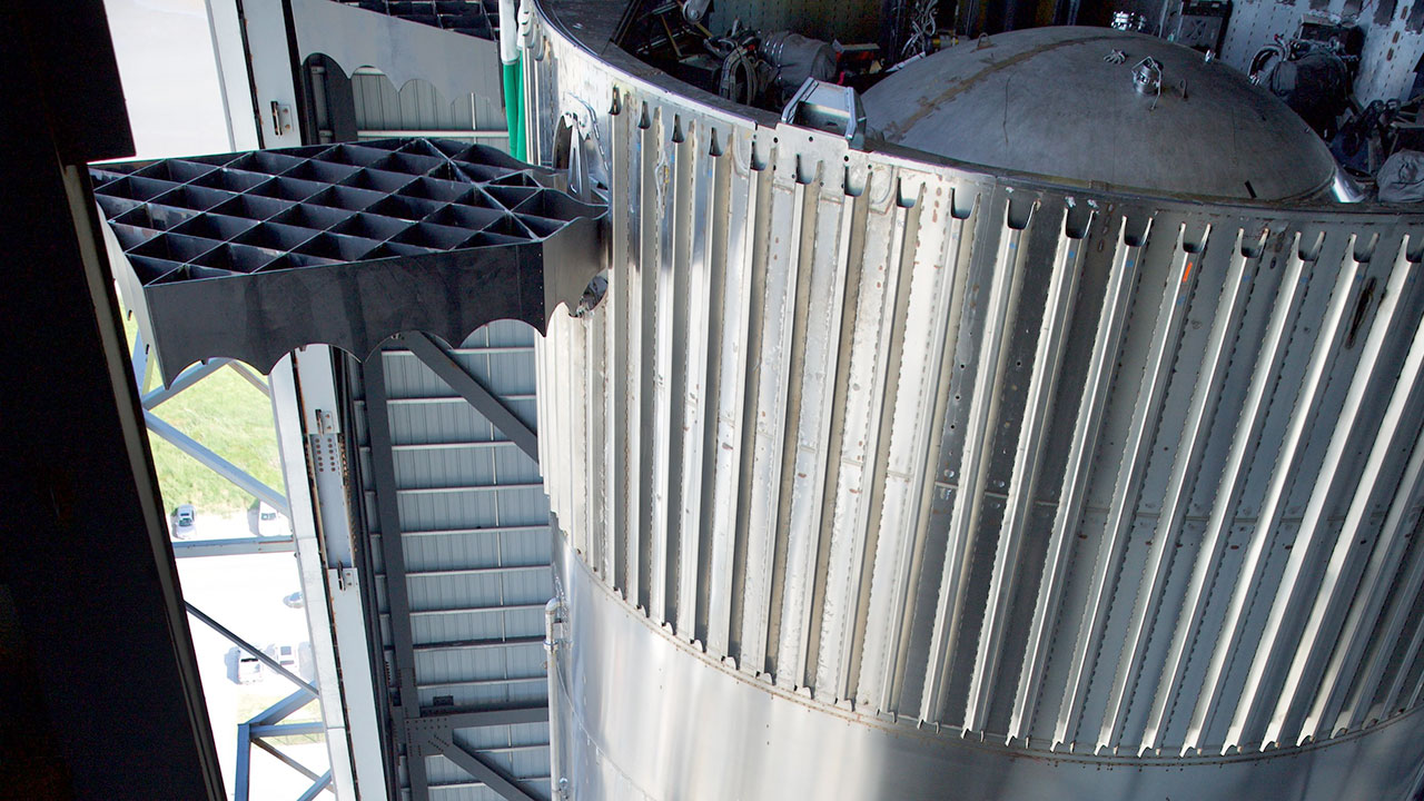
It certainly does look like a booster cap in there, that it's in there to protect the top of the booster. I'm tickled to see that they depicted that Soviet-style hot staging standoff, with the open, diagonal bracing that I was hoping for.
So, given the fact that the hot-staging maneuver seems to have worked flawlessly twice, I have questions about the change:
1- Why were you hoping for the Soviet lattice design?
2- Any thoughts on why SpaceX is changing it? Perhaps to accommodate the additional exhaust flow of 3 more Raptors?
3- Do you suppose they have data suggesting the dome was getting hammered too hard? Perhaps both reasons?
The grid fins look like they might be the same as on the current booster, but moved to a 90 degree spacing. Elon had said at one time that having four grid fins of that size was overkill, but they seem to be planning on keeping them. The lower placement could have to do with hot staging, and certainly it will impact the vehicle aerodynamics. I think it produces less stability, meaning more maneuverability. With computer control, the reduced stability shouldn't present any issues.
The exposed engines are probably Raptor 3s, with builtin cooling and other durability features. Certainly it results in the elimination of a lot of mass. I guess they're confident enough about engine reliability to not worry about armoring them against RUDs. Certainly having fewer exposed parts on the engine will help with surviving RUDs of adjacent engines.
The last thing I noticed is the buttons at the base of the boosters. There would be four of them. The only thing that comes to mind is that they could be thrusters, but if they have gimbaling engines, why bother? Or will they eliminate gimbaled engines (weight and complexity) and go with lateral thrusters? Or is that just robbing Peter to pay Paul?
In ITF-3, the booster was clearly struggling for stability, as seen by the video of the grid fin working overtime to try and stabilize it. There's conjecture that the resulting fuel slosh prevented Raptor relight issues, which would have negated gimbaling Raptors from even being operational. I wonder if the change in grid fin position (lower) as well as the addition of bottom thrusters are to attempt to address that.
Also, are these top-thruster ports that are now gone?:
We do not know if the test flight hot stagings have worked “flawlessly” or not. It is possible that SpaceX had sensors at the top of the booster that indicated damage occurred.given the fact that the hot-staging maneuver seems to have worked flawlessly twice, I have questions about the change
Or perhaps the new diagonal design is lighter and just as strong. It also provides increased spacing between the ship engines and the top of the booster which over multiple booster reuses could be advantageous because of decreased wear on the top of the booster.
We do not know if the test flight hot stagings have worked “flawlessly” or not.
Sure... hence "seems to have" in my post.
It is possible that SpaceX had sensors at the top of the booster that indicated damage occurred.
Right, that was my #3, to your point, the damage may have been to the ring itself, and not the dome I suppose...
Or perhaps the new diagonal design is lighter and just as strong.
It would be interesting to know what the weight difference is...
It also provides increased spacing between the ship engines and the top of the booster which over multiple booster reuses could be advantageous because of decreased wear on the top of the booster.
Right... again my #3...
")
It's superior by almost any metric. It should be lighter, stronger, and provide more area for exhaust to pass.1- Why were you hoping for the Soviet lattice design?
Because of the above. The question is why SpaceX went with the current design at all. I'd say it's because SpaceX worked with the materials, processes and skills they had on hand. They do rings, cutouts and stringers. There was no reason to build up the materials, processes and skills needed for the Soviet design until they figured out if they could even use hot staging. So the current design was a proof of concept, and now they can design a better version of the system. It's a pretty standard SpaceX approach to problem solving.2- Any thoughts on why SpaceX is changing it? Perhaps to accommodate the additional exhaust flow of 3 more Raptors?
As I can now view the current hot staging ring design as a prototype, I don't think they particularly cared one way or another. The rings were throwaways, and existed only to allow SpaceX to find out if they could hot stage the Starship stack. It was more of a control system issue than a hardware issue. The Soviet design should allow for as much standoff distance as they want (subject to the tower hardware's limitations).3- Do you suppose they have data suggesting the dome was getting hammered too hard? Perhaps both reasons?
I have no idea. IFT-3 could have been a control system issue, or they underestimated the consequences of trying to light the engines with so much airflow, etc. The choice to go with uniform spacing on the grid fins could be almost anything. I wonder if that will complicate getting them through the doors of the construction bays. As I recall, it's already a pretty tight fit.In ITF-3, the booster was clearly struggling for stability, as seen by the video of the grid fin working overtime to try and stabilize it. There's conjecture that the resulting fuel slosh prevented Raptor relight issues, which would have negated gimbaling Raptors from even being operational. I wonder if the change in grid fin position (lower) as well as the addition of bottom thrusters are to attempt to address that.
Methane vents?Also, are these top-thruster ports that are now gone?:
Notice that they've completely changed the geometry of the top of the booster. There's a much larger distance between the top of the booster and the hot staging section. The external stringers are gone, probably moved to the interior, above the methane tank. Also, both booster tanks are slightly smaller, which matches up with Starship being slightly stretched.
It's superior by almost any metric. It should be lighter, stronger, and provide more area for exhaust to pass.
Because of the above. The question is why SpaceX went with the current design at all. I'd say it's because SpaceX worked with the materials, processes and skills they had on hand. They do rings, cutouts and stringers. There was no reason to build up the materials, processes and skills needed for the Soviet design until they figured out if they could even use hot staging. So the current design was a proof of concept, and now they can design a better version of the system. It's a pretty standard SpaceX approach to problem solving.
As I can now view the current hot staging ring design as a prototype, I don't think they particularly cared one way or another. The rings were throwaways, and existed only to allow SpaceX to find out if they could hot stage the Starship stack. It was more of a control system issue than a hardware issue. The Soviet design should allow for as much standoff distance as they want (subject to the tower hardware's limitations).
I have no idea. IFT-3 could have been a control system issue, or they underestimated the consequences of trying to light the engines with so much airflow, etc. The choice to go with uniform spacing on the grid fins could be almost anything. I wonder if that will complicate getting them through the doors of the construction bays. As I recall, it's already a pretty tight fit.
Methane vents?
Notice that they've completely changed the geometry of the top of the booster. There's a much larger distance between the top of the booster and the hot staging section. The external stringers are gone, probably moved to the interior, above the methane tank. Also, both booster tanks are slightly smaller, which matches up with Starship being slightly stretched.
Yeah, I noticed the stringers gone as well.. also some change to the external raceways/piping.
What do you mean by "both booster tanks are slightly smaller, which matches up with Starship being slightly stretched." Where are you seeing this?
Look at the position of the grid fins. They are on top of the methane tank dome. The Starship 2 booster's grid fins are lower, so the vertical height available to the two tanks is reduced. That means less volume.What do you mean by "both booster tanks are slightly smaller, which matches up with Starship being slightly stretched." Where are you seeing this?
Then, according to the supplied numbers, Starship 2 gets a 1.8 meter stretch, allowing it to carry a little more propellant - assuming that the stretch is in the tank section, which appears correct.
I just noticed that the forward flaps on Starship 2 are closer to the nose, which simplifies the heat tile pattern. It should also provide greater control authority, and either move the flaps farther from the lift points, or move the lift points closer to the nose as well. The higher lift points would help with stability of a loaded Starship.
Last edited:
I just looked it up, and that's one ring section taller, which I'm sure is no surprise to anyone. Each ring section is 1.82 meters in height.Starship 2 gets a 1.8 meter stretch
One more thought on gimballing engines versus thrusters.
The only time the middle ring of engines needs to gimbal is during the turn for the boostback, right? So why not fire the 13 engines, gimbal the center 3, and use thrusters to produce the rest of the turning moment? During descent, you certainly don't need 13 gimbaling engines, and during landing you're only firing 3 engines. So the gimbals on the middle ring of 10 engines don't do very much, and I'm sure there some heft to the machinery, along with cost and potential for failures.
Assuming that those dark spots are thrusters:
They went with gimbals for the middle ring because it simplified flight testing. They didn't have to get both gimbals and thrusters working to perform the turn for boostback.
Also, if the geometry of a boostback turn is strictly defined, then they'd only need thrusters for that specific maneuver. That said, they might use such thrusters during tower catches. Use the gimballing engines to balance the stick on its end, and use the thrusters to translate over to the catch point. There may not be any need for the thrusters, given precise enough control over the engines.
And yes, I acknowledge that the thrusters represent another system with its own failure modes. If it can be kept simple enough, it would seem to be a clear win.
nativewolf
Active Member
While I appreciate the thought, I'm just a software engineer with enough knowledge of engineering and physics to sound like I might know what I'm talking about.While I appreciate all the detail...doesn't EM hate for you to spend office hours on the forum?
I don't.
But I did stay at a Holiday Inn Express last night.
nativewolf
Active Member
The answer is that it would be dumb to use thrusters on the bottom of the booster to assist in the turn because that's where the bulk of the mass is. You want the booster to rotate, not translate, and the best way to do that is to have thrusters at the top, away from the center of mass, like the Falcon 9 booster.So why not fire the 13 engines, gimbal the center 3, and use thrusters to produce the rest of the turning moment?
If the blobs on the image are thrusters, then they would be most appropriate for use during landing/catching. They can provide good translation control. Without them, the booster will have to lean in the direction that it wants to go. The more aggressive you want your translation, the harder the lean would have to be. That may not work well when in close proximity to the tower.
Look at the position of the grid fins. They are on top of the methane tank dome. The Starship 2 booster's grid fins are lower, so the vertical height available to the two tanks is reduced. That means less volume.
Then, according to the supplied numbers, Starship 2 gets a 1.8 meter stretch, allowing it to carry a little more propellant - assuming that the stretch is in the tank section, which appears correct.
I just noticed that the forward flaps on Starship 2 are closer to the nose, which simplifies the heat tile pattern. It should also provide greater control authority, and either move the flaps farther from the lift points, or move the lift points closer to the nose as well. The higher lift points would help with stability of a loaded Starship.
So, if the booster tanks are smaller, yet Booster prop load increases in that configuration:
Does that imply that imply for flight 3 they just weren't full?
Ah, the idea of having bottom thrusters in order to perform translation maneuvers for catching is an interesting one.The answer is that it would be dumb to use thrusters on the bottom of the booster to assist in the turn because that's where the bulk of the mass is. You want the booster to rotate, not translate, and the best way to do that is to have thrusters at the top, away from the center of mass, like the Falcon 9 booster.
If the blobs on the image are thrusters, then they would be most appropriate for use during landing/catching. They can provide good translation control. Without them, the booster will have to lean in the direction that it wants to go. The more aggressive you want your translation, the harder the lean would have to be. That may not work well when in close proximity to the tower.
I didn't notice the numeric difference.Does that imply that imply for flight 3 they just weren't full?
Looking at the IFT-3 footage, the LOX tank doesn't look topped up, so I assume the methane tank wasn't either. Beyond that, I suspect that they didn't "super-chill" the propellants for the early test flights. If V2 does that, then it would gain 8-10% on the propellant load by mass. That, combined with whatever they didn't load on IFT-3, may make up the 350 ton difference.
This would be certainly be consistent with Elon's tendency to use fully-optimized numbers for future vehicles.
I didn't notice the numeric difference.
Looking at the IFT-3 footage, the LOX tank doesn't look topped up, so I assume the methane tank wasn't either. Beyond that, I suspect that they didn't "super-chill" the propellants for the early test flights. If V2 does that, then it would gain 8-10% on the propellant load by mass. That, combined with whatever they didn't load on IFT-3, may make up the 350 ton difference.
This would be certainly be consistent with Elon's tendency to use fully-optimized numbers for future vehicles.
Hmm.. I thought I remembered some discussion of new higher-capacity chillers being installed at Starbase allowing for faster prop load times... and that indeed the booster was filled faster for IFT-3, implying they were in use. I guess that doesn't mean the temp dial was turned all the way down....
This isn't really true. Gimballing engines can provide translation without a lean. It's more complex to do both hover and translation only using the engines because it means precise control over both angle and thrust level, but the requirements may be well within the vehicle's capabilities. Still, horizontal thrusters would make control simpler, with the engines providing lift (and roll) and the thrusters providing translation.Without them, the booster will have to lean in the direction that it wants to go.
I look forward to seeing what those blobs are. They'll probably end up being something mundane like communications arrays or some such thing.
Similar threads
- Replies
- 3
- Views
- 749
- Article
- Replies
- 203
- Views
- 6K
- Replies
- 667
- Views
- 29K
- Replies
- 93
- Views
- 5K