


Welcome to Tesla Motors Club
Discuss Tesla's Model S, Model 3, Model X, Model Y, Cybertruck, Roadster and More.
Register
Install the app
How to install the app on iOS
You can install our site as a web app on your iOS device by utilizing the Add to Home Screen feature in Safari. Please see this thread for more details on this.
Note: This feature may not be available in some browsers.
-
Want to remove ads? Register an account and login to see fewer ads, and become a Supporting Member to remove almost all ads.
You are using an out of date browser. It may not display this or other websites correctly.
You should upgrade or use an alternative browser.
You should upgrade or use an alternative browser.
Wireless front parking camera with monitor for front bumper protection
- Thread starter artsci
- Start date
-
- Tags
- Model S User Interface
This morning I bench tested all of the cables and pinouts to make sure all of the connections were correct before I plug the switching PCB board into the $6,000 touchscreen. Good thing! The cable kit from China inverts the pinouts, so if I had assumed the pinouts were the same as the Tesla cables I might have done some damage. The fix was simple: The Fakra receptacles on the PCB just have to be flipped 180 degrees. The circuit itself is fine. But I now have to make a new PCB, so I can solder the correct receptacle orientation.
This, of course, will make the China cable kit a must for this mod, at least with the PCB we're developing. That's ok, as the Tesla cables take a very long time to acquire and they're way too long for this application.
This, of course, will make the China cable kit a must for this mod, at least with the PCB we're developing. That's ok, as the Tesla cables take a very long time to acquire and they're way too long for this application.
JerryNycom
Member
Awesome Rick! Is it possible we can mount the camera so we can see a parking curb without guessing its 12 inches away under the car?
Awesome Rick! Is it possible we can mount the camera so we can see a parking curb without guessing its 12 inches away under the car?
I don't think the mounting position will matter much in judging the distance of close objects. It's an extreme wide angle camera that distorts perspective and makes things look closer than they actually are. So after a few tries you learn to accurately judge the distance of objects on the touchscreen.
Everything is now set up for the test of the PCB camera switch tomorrow.
Contrary to my earlier posts about problems with the Oracle remotes, I've had an Oracle four channel remote sitting around unused and untested for several months so I thought I should try to program it with Homelink to control the camera switch relay and turn on and off the lighted T. This time everything worked like a charm. Programing took less than 15 seconds for each device and worked very reliably. I ran the 12v and ground leads from the Oracle control box to power the PCB relay that switches the camera views on the touch screen. So now the camera switch can easily be controlled from Homelink, and I now can turn the lighted T on and off from the touchscreen. No push button or toggle switches needed. I was very happy about this, as it's a simple solution as opposed to adding mechanical switches to a car than has none or adding to the PCB a rolling code receiver to sync with Homelink. Here's a photo of the Homelink set up.
Tomorrow I'll test the PCB. Fingers crossed.
WhiteP85
Member
Worth a shot. You may be on to something: amzn.com/B00DN2U0YI - so I ordered one. Thanks for the idea. Will post what I find when it arrives.
(My neighbors would not even see that.)
My mirror arrived and I taped it as close as possible to the back camera as shown here:
On the console it looks like this:
You can see the mirror image in the rectangle in the center. The sense is correct. Unfortunately the mirror is still not optically close enough to the wide angle lens. It would probably work with a different lens and perhaps if the lens was cut away but I am afraid that this does not look like an easy solution with this mirror and lens combination.
Connected up the PCB a few hours ago. Disappointment. I only plugged in the rear camera. Got an immediate error message: "No camera detected." WhiteP85 and I think that Chinese made connecting cables may be the problem and I've contacted the maker to see what can be done. The pinouts are different and the twisted pairs do not appear to be twisted. Either is a problem. I figured I had solved the pinout problem by changing the PCB traces but perhaps I made a mistake. Going to check all of that. I'm going to recheck the all of the cable connections as well.
I didn't come this far to fail and conceptually there's no reason why this shouldn't work. I'm going to keep at it until we have a solution.
I didn't come this far to fail and conceptually there's no reason why this shouldn't work. I'm going to keep at it until we have a solution.
Akikiki
A'-Lo-HA ! y'all
Rick, Thanks for the report on the test. I received my Chinese cables purchased on the ebay link. Sure glad now that I had not tried to begin routing them through access points to their proper destinations. Now, I will wait for more info from you.
Rick, Thanks for the report on the test. I received my Chinese cables purchased on the ebay link. Sure glad now that I had not tried to begin routing them through access points to their proper destinations. Now, I will wait for more info from you.
Yes, don't do anything with those cables until we get the pinouts resolved. But based on some illustrations sent to me by others I'm now quite sure that the issue is my PCB circuit.
Update: As it turns out, there's nothing wrong with the Chinese cables. Studying the drawings below, which were provided by another owner, it's clear to me that the problem is my PCB circuit -- I think both the connections from the cameras and the connection to the touchscreen are wrong. I tested the pinouts for the Chinese cables and they match the drawings (the colors of the wires are just different).
I'll correct the PCB and make a new version for testing as soon as I can.
Last edited:
JerryNycom
Member
Got my cables today as well.....Patiently waiting for your PCB goodness!
After another test connection, I've now determined that the cable pinouts and the PCB board circuits are not correct. I've corrected the PCB board, but don't use the cables. I've given RF supplier the correct pinouts and they'll be making a correction. I'm waiting to hear from them about what they'll do to replace all the sets they've shipped. But I can promise they'll replace them all free of charge. They're shipping me a corrected set for testing before they replace everyone else's
@artsci Wow wasn't expecting free replacement. You take good care if us, thanks for negotiating that.
Just heard this morning from RF Supplier in China. They are shipping a set of the corrected cables to me for final testing. Assuming they're correct we'll then arrange replacements for everyone who's ordered a set. This should take 1-2 weeks. In the meantime I'll be able to test the PCB circuit with the correct cables and if it works, get the PCB's into production.
Last edited:
Seven7
Member
I haven't read the whole thread, but when you get it working perfect,have them in stock- and it can be installed easily by a good stereo shop, I'll take one. I'm in no rush. Thanks!! Joe
I haven't read the whole thread, but when you get it working perfect,have them in stock- and it can be installed easily by a good stereo shop, I'll take one. I'm in no rush. Thanks!! Joe
Should be a simple install for a stereo shop. The toughest task is mounting the front camera and running the cable behind the nose cone through the grille area.
Warrenbonz
Member
I haven't read the whole thread, but when you get it working perfect,have them in stock- and it can be installed easily by a good stereo shop, I'll take one. I'm in no rush. Thanks!! Joe
+1
")
... I am afraid that this does not look like an easy solution with this mirror and lens combination.
A few weeks ago I tried some front-surface mirrors and some prisms I had around, not really a workable solution as you showed and i'm sorry I did not post to save you the effort.
Another idea for switching. The CAN bus has the backup light. You could rig the front camera to be on the screen all the time and only switch to back facing camera when a triggered switch is thrown. This saves the whole Homelink two button push suggestion I had earlier.
Last edited:
WhiteP85
Member
Time for a little technical update. Artsci and I have been collaborating on the front camera design and we thought it would be useful to summarize where we are:
First the Goals:
Primary
The basic Design Approach:

The Main Challenge:
The Tesla rear camera image will be mirrored if used as the front camera
How do we flip the front camera image?
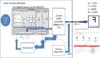
Block Diagram of what we know:

Progress to Date:
Open Questions:
A link to this info as a presentation with additional info on the draft PCB schematic is here: https://docs.google.com/presentation/d/1GA7W1JhuouDdKC0KSRIWPwN6Xie7xU6LxFPRIPGjeTc/edit?usp=sharing
First the Goals:
Primary
[*=1]Add front facing camera to the Model S that displays on the existing screen
[*=1]Switch the camera using the Tesla Homeport remote
[*=1]Include parking option to toggle from front camera to rear camera when the car shifts to reverse
[*=1]Add video recording options for both front and back camera
[*=1]Optionally combine video signal so that front and back can be displayed
The basic Design Approach:
The Main Challenge:
The Tesla rear camera image will be mirrored if used as the front camera
How do we flip the front camera image?
[*=1]Modify the existing Tesla Camera?
[*=1]Source or build a compatible new camera?
[*=1]Use an optical lens (difficult with wide angle lens as tested)?
Block Diagram of what we know:
Progress to Date:
- artsci sourced Fakra connectors and cables for LVDS HDS cable. Initial cables faulty new ones on order
- Press release identified that Omnivision OV10630 video sensor is used by Tesla
- ken830 found link to very similar if not identical OV10633 data sheet that explained the image mirror settings
- artsci tested Oracle LED remote switch using Tesla Homelink - alternative to internal remote decoder below
- WhiteP85 sourced and tested chinese RF remote decoder that can be built into camera switch using Homelink
- artsci opened up camera and ken830 identified PIC microcontroller that may be controlling image mirror
- WhiteP85 and artsci measured LVDS cable pinouts and demonstrated that the camera image still works with non ideal wiring in-line with the cable. This means that the relays will likely work to switch the signal
- WhiteP85 working on camera switch design
Open Questions:
- Is there a third-party supplier of a compatible LVDS output camera module?
- Is there an easy way to mirror the rear camera image on the existing camera?
- Is the block diagram shown correct? Anything missing?
- Assuming that the control register shown controls the mirror
- Is the I2C/SCCB slave interface set locally using the PIC or remotely using the console? i.e. is the SCCB included and used in the serializer as shown by some serializer datasheets
- Is this set once and saved in memory or reset every time the camera is powered on?
- What serializer chip is used?
- What does the PIC do? SCCB control? Supply SVCLK and if so what frequency?
- What are the critical register settings? i.e. format YUV, RAW settings etc?
- We would love a schematic and all the register settings but that might be too much to ask.
A link to this info as a presentation with additional info on the draft PCB schematic is here: https://docs.google.com/presentation/d/1GA7W1JhuouDdKC0KSRIWPwN6Xie7xU6LxFPRIPGjeTc/edit?usp=sharing
Attachments
Last edited:
Similar threads
- Question
- Replies
- 3
- Views
- 720
- Replies
- 87
- Views
- 17K
- Replies
- 1
- Views
- 884
- Replies
- 5
- Views
- 2K