Welcome to Tesla Motors Club
Discuss Tesla's Model S, Model 3, Model X, Model Y, Cybertruck, Roadster and More.
Register

$8,000 for a Charger in my Apartment Building: Request for better ideas...

This site may earn commission on affiliate links.
NEMA 10 (hot-hot-neutral) outlets are not allowed for new installations because they don't have a ground. NEMA 6-30 is available but not common (hot-hot-ground). NEMA 14-30 (hot-hot-neutral-ground) is the most common for 30 amp sockets. Tesla does have 14-30 adapters.

Having a conductive conduit does not allow you to eliminate the ground conductor.

A 30 amp circuit requires 10 AWG wire. It is even shown at that link you provided.

Romex cannot be left exposed. It must be protected like behind drywall. If you need to run the cable on the surface, you're better off with THHN single conductors in conduit unless most of the run is in a crawl space or something and only the last several feet are on the surface.

Thank you for the useful information and advises.

I made some progress regarding my EV plug installation in my garage.

I plan using AWG #6 stranded copper (hot-hot-neutral) and #10 (ground) in a 3/4 metal conduit, about 150 ft long.
(The Neutral will not be really used by the Tesla ESVE, but still I think that I need to use AWG #6 for the neutral)

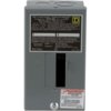
I installed a sub panel with a dual 30 A breaker near the main panel and meter.
I prefer not making any change to the main panel, such as using tandem circuit breakers.

At the other end of the line, I have a fused 30 A safety switch and a NEMA 14-30 plug.

The Tesla NEMA 14-30 adapter is still out of order, I hope getting it by the time of completion of this project
otherwise I will have to temporally convert my system to use a NEMA 10-30 plug.

The Tesla Corded Mobile Connector and will be kept in a (19" x 14") Steren lockable cabinet when not used.
There is a small watt meter display to provide some consumption and charging efficiency information.

Here is a view of the cabinet:
2018 11 28 - EVSE Cabinet - closed .jpg 2018 11 28 - EVSE Cabinet - open .jpg

- I'm now a little puzzle for connecting the 30 A breaker sub panel to the main 60 A breaker panel.

The main panel uses Romex #3 Stranded aluminium so I cannot mixed the AWG #6 stranded copper together.

My first thought would be connecting the sub panel to the main panel using #6 stranded aluminium wires
but I cannot find such wires sold by the feet (I only need a bout 5 ft)

Another solution would be to use a junction box to create a clean split 'Y' connection line,
to isolate the two types of wires, using connection bar strip for each wire.

But so far I didn't find find such type of junction box, especially for larger size wires,
and connection bar strip seems to be reserved for ground or neutral type of connection.

A good solution would be using a DCC EV energy management system, but still I would need
to use some additional wiring to connect the DCC box to the main panel.

I suppose that few people have been in a similar situation, and I would be interested getting some
advises or recommendation for connecting wires to a main panel or splitting lines in a clean and safe way.
 
It's not clear to me how you will connect the new sub-panel to the main panel. If you only have one breaker in the sub-panel, there is no real advantage to adding the sub-panel because you would need to feed it from a breaker in the main panel. That breaker could be wired directly without a sub-panel.

I am guessing that you imagined that you could somehow connect the sub-panel to the main feed without adding anything to your main panel. I can't think of a code-compliant way to do that off the top of my head. Please take pictures of what you have (preferably with covers both on and off) and post them here. Otherwise, consult an electrical contractor to see if they have a way to accomplish what you want to do.
 
It's not clear to me how you will connect the new sub-panel to the main panel.
If you only have one breaker in the sub-panel, there is no real advantage to adding the sub-panel
because you would need to feed it from a breaker in the main panel.
That breaker could be wired directly without a sub-panel.
The main panel is shared with other units.
All the Romex cables are located under the 'brown' box cover.
The Romex are connected to each individual breaker above each meter.
There is nothing wrong with the code for connecting a controlled DCC box to the main panel breaker.
The problem is the use of aluminium for the Romex and copper for the EVSE.

20181014_215041.jpg
 
#6 stranded Aluminum, by the foot.

XHHW-2 Aluminum Wire | Wire & Cable Your Way

And I see davewill has already mentioned the Polaris connectors.

Just for the record, I'm not a big fan of screwing with aluminum. The likelihood of a novice burning something down is MUCH higher with aluminum, IMHO.

Make sure whatever you are connecting the aluminum to is rated for aluminum use. I don't believe every panel is.

Do you intend to double-tap(two sets of wires) the main breaker? I'm not at all sure that's allowed, and I doubt you'll have space for the extra wire in there anyway.
 
You might be able to use Polaris connectors inside an otherwise normal junction box.
They are good for both copper and aluminium.

Manufacturer of Aluminum and Copper set screw connectors for the Utility, OEM, and Contractor and Industrial Markets

Thank you for the link to the Polaris connectors.

I have seen before some splitters allowing to connect two wires, in particular when using two different types of electric conductors,
but I didn't now about the isolated multi-conductor connector. There are a quite large variety.

It seems that the IPL model corresponds to the range size of AWG wires I am using.

This could be a good solution for taping an extra line,
I would need then to find a good fitting junction box, and connect the end of the Romex cable to it.

Do you intend to double-tap(two sets of wires) the main breaker?
I'm not at all sure that's allowed, and I doubt you'll have space for the extra wire in there anyway.

This is something that I would like to avoid, and I don't think that I could insert another wire.
I don't like also to have to play with aluminium, as the stranded wires are not very flexible and break easily.

I could replace the original 60 A main circuit breaker with a tandem circuit breaker,
but the one I found are like 60A / 40A I doubt that the main feeder has an Ampacity of 100A.

I don't think this would be allowed with the code and also if other EV plug get installed using tandem circuit breakers,
the street main feeder will become quickly overloaded.

Since I have a 60 A input feeder, I prefer stay safe with a 30 A EVSE system (which will be set to 24 A anyway).
The other loads during night time, except some lightning, would be only a 30" type 3 refrigerator on one phase,
and a microwave on the other phase. I don't have AC or Washer and Dryer.

The following picture show the main circuit breaker and the above empty location where I could instal a connection box.
 
You might be able to use the Polaris connectors to do the split right there inside the pictured breaker panel. Use a copper pigtail from the breaker to the split, then connect the existing conductors and the new feed to that. With a 60a breaker, the new wire would also need to be sized for 60a, but I think you knew that. That also makes it convenient to run a neutral and ground right from there.

OTOH, I wouldn't assume that the tandem breaker is a no-go. Get some expert advice on that. It would be by far the cleanest install. It would also be nice to be able to kill power to the new circuit without having to kill the power to your home.
 
You might be able to use the Polaris connectors to do the split right there inside the pictured breaker panel.
Use a copper pigtail from the breaker to the split, then connect the existing conductors and the new feed to that.
With a 60a breaker, the new wire would also need to be sized for 60a, but I think you knew that.
That also makes it convenient to run a neutral and ground right from there.
This an excellent idea, this would be even cleaner than adding a connection box.
I would have to make an additional hole for the additional raceway, I think I can find a tool to make such hole.
20181205_204531ext2 .jpg

The Polaris connectors can be find on Amazon or e-Bay but it would be more convenient if I can find then locally
to be sure about which model to get and fit with my wires.

About the 60 A cable, it seems that I have to use at least AWG #4 or #3, I will get some to check which one would
be compatible with the breaker connector size. AWG #4 Ampacity is 70 A and AWG #3 Ampacity is 100 A.

OTOH, I wouldn't assume that the tandem breaker is a no-go. Get some expert advice on that.
It would be by far the cleanest install.

It would also be nice to be able to kill power to the new circuit
without having to kill the power to your home.
A tandem breaker would overload the main feeder, so this would be a 'cheating' solution.

I plan putting a local sub panel with a circuit breaker next to the main circuit breaker,
so I can isolate the new additional circuit from the main feeder.

square-d-individual-subpanels-qo2l30scp-64_1000.jpg
 
Getting back to @rachelhikes. Any update? Totally commend you for pursing this.

As someone who charges at home now instead of going to the gas station, it’s just so easy to do and it takes less of time to plug in and remove when completed charging than driving to the gas station and pumping to fill up. There’s someone always at our home so unfortunately even with PG&E analysis the plans don’t work to our advantage so I think we are paying $.28kWh but still feel it’s worth it. We’ll eventually add solar. When more people realize this convenience to “fill up” at home I can see it helping move EVs forward. Of course legacy building/wiring infrastructure can make people give up on it. So glad you are tenacious. Sounds like you are close.
 
Last edited:
About the 60 A cable, it seems that I have to use at least AWG #4 or #3, I will get some to check which one would
be compatible with the breaker connector size. AWG #4 Ampacity is 70 A and AWG #3 Ampacity is 100 A.

If the breaker is 60A, why would you need to use 70A wire if your job gets harder as a result?

Yes, you do definitely have to be concerned with the wire size the breaker size would accept. IIRC, I had a 60 amp breaker and it would take no more than 6AWG.

On the topic of making another hole, can you just put your new subpanel in the pathway to the the main panel, and connect through it? You might have to add a pigtail to get to the main panel from the subpanel, but that's no big deal.

On the topic of the nicely secured lockable box.... I believe one of the latest updates makes the charging handle not be locked into the 3, so you might find your UMC gone someday, unless you build some sort of lockable sub-box or cage for the main body of it.
 
By the way, you really only need 8 gauge to get 24amps(or even 30) at the plug 150' from the subpanel. Probably not worth the difference, but thought I'd mention it.

I went back to earlier portions of this thread, and it looks like you were already considering my suggestion of having the subpanel do the splitting for you.

If you do the splitting in the main panel, make sure you use one of the knockouts, don't even think of cutting your own. Also, there are split-stress-reliefs so you could knockout a slightly larger ring(probably two sizes up) from the knockout that's already been knocked out, and install two independent cables in it, each in their own cubby. Alternatively, and this may be frowned upon, you could run them both through the same single knockout(might need to be bigger anyway), piggybacked. I've never seen that done with large-gauge wire, though.
 
On the topic of the nicely secured lockable box....
I believe one of the latest updates makes the charging handle not be locked into the 3,
so you might find your UMC gone someday,
unless you build some sort of lockable sub-box or cage for the main body of it.
I tested that I can still lock the cabinet containing the portable UMC even if the cable is going outside of the cabinet.
But I will check if there will be not heat concern, or I can add some vents to provide some air circulation, or just keep it open when in use.

The Tesla plug stay locked during the charging and it's a private garage.
The NEMA 14-30 is very hard and difficult to unplug so I'm not too worry about the portable UMC been stolen.
I'm more concerned about someone a little bit too curious and touching any electrical wire.

I think you were making reference about the unlocked adapter when using a public L2 charger.
So I build a plastic cover, using a coffee mug holder, for my J1772 plug that I use when leaving my car at night for charging,.

20181030_201154.jpg 20181114_151535.jpg
 
If the breaker is 60A, why would you need to use 70A wire if your job gets harder as a result?

I am considering the Ampacity of each wire:

- AWG 6 Stranded Aluminium - Ampacity 40 Amps
- AWG 4 Stranded Aluminium - Ampacity 55 Amps
- AWG 3 Stranded Aluminium - Ampacity 65 Amps
- AWG 2 Stranded Aluminium - Ampacity 75 Amps

- AWG 6 Stranded Copper - Ampacity 55 Amps
- AWG 4 Stranded copper - Ampacity 70 Amps
- AWG 3 Stranded copper - Ampacity 100 Amps
- AWG 2 Stranded copper - Ampacity 115 Amps


Yes, you do definitely have to be concerned with the wire size the breaker size would accept.
IIRC, I had a 60 amp breaker and it would take no more than 6AWG.

You are correct, I will have to go with circuit breaker wire size. I have some AWG #6 stranded copper,
so I will compare the wires size with the aluminium wires.

On the topic of making another hole,
can you just put your new subpanel in the pathway to the the main panel, and connect through it?

This not really possible. The Romex wires are connected to the circuit breakers and immediately disappear into the ceiling.
Also I don't like to play too much with aluminium wires.

What I plan to do is to have a 'Y' junction in the path of the main panel.
And from this 'Y' junction I will be able to branch out a wires to connect the subpanel and the 30 A circuit breaker.
There is about 5 feet between the the main panel and the subpanel.

You might have to add a pigtail to get to the main panel from the subpanel, but that's no big deal.
I'm sorry but I cannot really follow what you try to explain to me.

By the way, you really only need 8 gauge to get 24amps (or even 30) at the plug 150' from the subpanel.
Probably not worth the difference, but thought I'd mention it.
I think you are right, I could downsize a little bit the wires and use #8 instead of #6,
which will help a lot when putting the 4 wires into the raceway.

Using stranded copper wires:

AWG 10 - Ampacity 30 Amps
- maximum length for a 3% voltage drop and 30 A is 93 ft.
- maximum length for a 3% voltage drop and 24 A is 116 ft.

AWG 8 - Ampacity 40 Amps
- maximum length for a 3% voltage drop and 30 A is 148 ft.
- maximum length for a 3% voltage drop and 24 A is 185 ft.


AWG 6 - Ampacity 55 Amps
- maximum length for a 3% voltage drop and 30 A is 235 ft.
- maximum length for a 3% voltage drop and 24 A is 294 ft.


If you do the splitting in the main panel, make sure you use one of the knockouts,
don't even think of cutting your own.

Also, there are split-stress-reliefs so you could knockout a slightly larger ring(probably two sizes up)
from the knockout that's already been knocked out, and install two independent cables in it,
each in their own cubby.

Alternatively, and this may be frowned upon, you could run them both through the same single knockout(might need to be bigger anyway), piggybacked.
I've never seen that done with large-gauge wire, though.

Honestly, adding a new knockout would be very helpful, but also would be tricky to make:
Increasing the size of the knockout would be as difficult.
Using a junction box might be simpler finally.

20181205_204502.jpg
 
Last edited:
BTW, My install uses a small load center in lieu of a traditional subpanel. Might be the thing for your install as it's small and unobtrusive.

20181207_111202.jpg IMG_20180613_143630.jpg 20181207_111435.jpg

A 40a breaker in the main panel feeds the submeter shown, then goes to the load center that holds a 40a breaker for my EVSE. I had to do this because the special rate program I was in when it was installed required a submeter and an exterior cutoff (I never got a satisfactory answer why the breaker in the main panel couldn't serve for that). Now, I just have my own meter installed for info purposes.
 
Last edited:
I think that may be an unwarranted assumption. The decision about whether the panel is overloaded usually rests on the loads that are connected, not the size of the breakers. Get an electrician to do a proper evaluation of the install.
Hi, it's a 30 units dwelling, each unit has a 60 A and two phases,
the shared utility has a 100 A tri phases, mostly for the elevator,
dryers are gas, and the main feeder is a 600 A tri phases.
There is no AC, only gas heaters in the units for the winter.
Each unit has an electric range and oven.

I don't know how the total load is calculated, but 600 A doesn't gives too much margin...
I don't want to take more load than 60 A to be fair with other people, especially if other people starts to get an EV.
That's my point. You're going to "take" the same amount whether you install a tandem breaker or not. The only question is whether the install meets code. I know I'm not qualified to figure that out, and I suspect that you probably need professional guidance on that as well.

P.S. It's not a matter of "fairness", after all you pay for every kWh you use, it's merely a matter of whether the install is safe and to code.
 
Last edited:
  • Helpful
Reactions: Rocky_H
A 40a breaker in the main panel feeds the submeter shown, then goes to the load center that holds a 40a breaker for my EVSE.
I had to do this because the special rate program I was in when it was installed required a submeter and an exterior cutoff
(I never got a satisfactory answer why the breaker in the main panel couldn't serve for that).
Now, I just have my own meter installed for info purposes.
I also added a small Digital Current Voltage Power Energy Analyzer just for the fun of it
Digital Current Voltage Power Energy Analyzer .jpg