Welcome to Tesla Motors Club
Discuss Tesla's Model S, Model 3, Model X, Model Y, Cybertruck, Roadster and More.
Register

$8,000 for a Charger in my Apartment Building: Request for better ideas...

This site may earn commission on affiliate links.
Make sure you are looking at the right ampacity charts for your application. THHN in conduit is rated a good bit higher than the NM-B numbers you seem to have quoted, but you need to have the right terminations at the ends to make it retain that 90c rating.

Ampacity Charts - CerroWire

I also was a bit concerned about stuffing 3x6awg and a 10awg ground through a 3/4" conduit, but at first look it looks 'okay'. I didn't look real hard.

My concern regarding the lock box is fine as long as you can lock it shut when charging. Without that, I fear you'd have a walkaway UMC. Not really a big problem in a private garage, anyway.
 
  • Like
Reactions: NeverFollow
That's my point. You're going to "take" the same amount whether you install a tandem breaker or not.
The only question is whether the install meets code.
I know I'm not qualified to figure that out, and I suspect that you probably need professional guidance on that as well.

P.S. It's not a matter of "fairness", after all you pay for every kWh you use, it's merely a matter of whether the install is safe and to code.
My main concern is to be safe, so even a 15 A (12A) would have fine.
Getting an EV plug at home is mostly for convenience, so far I have been using a public L2 at walking distance less than a mile away.

I got some estimate about this project and the information about been code compliant was:

- When taping a wire from the main feeder for the EVSE, you can get only 50% of the max load, so I am limited to 30 A (24 A) and 240 A
(honestly, except a refrigerator and some LED lamps, there is not too much running at night, since I'm using night discount time).

- The main breaker must be able to handle the worse case, so when the total power consumption of the main circuit breaker exceeds 80%,
the EVSE must be de-energizes automatically using a Disconnect Box.

There are some other information available from PG&E: CODE REQUIREMENTS FOR INSTALLING EVSE
 
Make sure you are looking at the right ampacity charts for your application. THHN in conduit
is rated a good bit higher than the NM-B numbers you seem to have quoted,
but you need to have the right terminations at the ends to make it retain that 90c rating.

Ampacity Charts - CerroWire
I was using the NEC Reference Tables and the Voltage Drop Calculator .xls from Build My Own Cabin to calculate the wires size.

I also was a bit concerned about stuffing 3x6awg and a 10awg ground through a 3/4" conduit,
but at first look it looks 'okay'. I didn't look real hard.
- I tested that I can have 3 AWG #6 and 1 AWG #10 in a 3/4" conduit,
however I have been able to optimize the raceway layout and I'm below 140 ft now.
Also from Sophias_dad above comment, I plan to use 3 AWG #8 and 1 AWG #10

My concern regarding the lock box is fine as long as you can lock it shut when charging.
Without that, I fear you'd have a walkaway UMC. Not really a big problem in a private garage, anyway.
Yes, I can still lock the door when the UMC cable is connected to the car.
 
...
- The main breaker must be able to handle the worse case, so when the total power consumption of the main circuit breaker exceeds 80%,
the EVSE must be de-energizes automatically using a Disconnect Box.

There are some other information available from PG&E: CODE REQUIREMENTS FOR INSTALLING EVSE
I didn't realize you were planning to use a disconnect box. This one looks like it would serve as your automatic disconnect, junction box and subpanel all in one:


DCC-9 The Best Solution for Electric Vehicle Charging in Condos
 
You might be able to use the Polaris connectors to do the split right there inside the pictured breaker panel.
After a taking a second look at it, it seems to me that there is not enough room inside the breaker panel,
and I find difficult to make a hole for the new feeder line going to the UMC.

Main Panel - Master  Breaker .jpg

Use a copper pigtail from the breaker to the split, then connect the existing conductors and the new feed to that.
With a 60a breaker, the new wire would also need to be sized for 60a, but I think you knew that.
That also makes it convenient to run a neutral and ground right from there.

I found the Polaris connectors, and I have been advice at the electric store to get a 6" x 6" x 4" junction box.

The junction box looks big, but I think that that the code requests to have 6" of wire length for each connection.
Since I have three lines of three wires AWG #6 and a ground wire AWG #10, this make a lot of loose wires in the box.

I created a AWG #6 pigtail to connect the breaker and the split, which replace the current Romex AWG #4 aluminium.

6x6x4 Connection Box - Polaris Insulated connectors  - Side View  .jpg

The most critical now is to find a place for the junction box and to keep the whole system sturdy.

There is enough room just above the main panel, but there are a lot of Romex cables
so I cannot attach the connection box to the wall.

I have been able to build an EMT raceway for the UMC cable.
The Romex and the pigtail to the breaker will use a flexible conduit.

But the connection box is now dangling about one foot away from the wall.
I'm currently using the raceway to hold the connection box but I think that
it would be better to have the box been hold in a very study way using
some braces, and use flexible conduits for the UMC cable instead of a raceway.

The following pictures show the experimental solution that I am working at this point.

UMC Panel  feeder raceway  .jpg UMC feeder raceway curb jump from wall  .jpg UMC feeder raceway from curb to dangling junction box .jpg Dangling Junction box .jpg Raceway continuation from junction box to wall attachement .jpg Detail of EMT raceway to wall attachement .jpg 09 Detail of 3-4 of inch Romex pass through .jpg

I'm a little bit puzzle at this point for finding a way to have the junction box been hold in a sturdy way.
.
I could move the junction box on the wall, but I would like then need to extend the Romex cable to reach the box,
thus requesting to have another smaller junction box.

I'm again open to any suggestions.
 
If you place the junction directly above the breaker box and use hard conduit from the breaker box to the junction box, that might provide enough support. My other thought would be to place the junction box on the far left where you've got that bent conduit coming out of the wall. There seems to be mounting space there.
 
If you place the junction directly above the breaker box and use hard conduit from the breaker box to the junction box,
that might provide enough support.
Thank you for your reply.
I will have then to relocate four Romex cables then, and extend them to pass on each side of the box?
And to extend each Romex, I will need an extra junction box for each of the three other Romex,
with three IPL 4-2 Polaris extension inside.

My other thought would be to place the junction box on the far left where you've got that bent conduit coming out of the wall.
There seems to be mounting space there.
This is the solution that I was considering but I need to extended the Romex by about 5 feet,
so I need to have another connection box just for this.

This second connection box would be a little bit smaller,
but still I need to put two cables of 4 conductors and 3 IPL 4-2 Polaris connectors.
This start to be an expensive solution too, each Polaris connection cost $16 and I need 6 of them and two boxes.

May be I could find at Home Depot, a combination of heavy duty metal brackets,
used to assemble wood studs, to hold the junction box tight.

I wonder what solution electricians do when working in a condo environment to add a new EVSE line?
 
Hmmm... If you rotated it so the open part of the box faced straight down, could you screw it to that piece of plywood?
This was my thought too.

This is the solution that I was considering but I need to extended the Romex by about 5 feet,
so I need to have another connection box just for this.
The higher you put the junction box on the wall, the more Romex you have to make the lateral distance. Everything else is new wire, so they can be longer to make up for the extra height.
 
How about you simply rotate the box in place so the opening is facing down, and screw a 2x4(or whatever) to the back of it and to the plywood that its seemingly right up against now anyway. It looks like there's also some fairly sturdy wood above the plywood, but it might be too far away to reasonably reach.

I'm REALLY surprised the apartment building is letting you screw with this, BTW.
 
  • Like
Reactions: KJD
How about you simply rotate the box in place so the opening is facing down,
and screw a 2x4 (or whatever) to the back of it and to the plywood
that its seemingly right up against now anyway.

It looks like there's also some fairly sturdy wood above the plywood,
but it might be too far away to reasonably reach.

I'm REALLY surprised the apartment building is letting you screw with this, BTW.
Thank you for all the above feedback!

- All the 'wood' panels are used purely to hide stuff, but they are not really sturdy and old, so I prefer not to screw anything on it.
Eventually they might be replaced in the future when doing some remodeling of the building.

- It's an older building, I have been helping the landlord doing some minor maintenance work.
I got some estimate from electricians, and it was like at least two days of labor, so you do the math.

I am not an expert, but I think that you need about a day to install the 150 ft conduit and another day to do all the wiring.

This depend of many factors, but also in a garage, you cannot really work when cars are present,
it's not possible to put a ladder between two cars, and there are not enough guest area to free spaces along the raceway.

After working a couple of hours above ground, using a drill hammer, or dealing with wires on curbing areas, you really need to take a break...
I am not in hurry so I prefer working on it on spare time to save cost, but the installation will be reviewed by an electrician.

- Putting the box horizontally is an excellent idea, as it would be easier to access the Polaris connector and wires, especially the aluminium Romex.

- I noticed that there is a one inch conduit just above, so it seems simple to attach the connection box to it
However, this conduit was not properly anchored so I plan to use some threaded rode up to the ceiling to consolidate everything.

- The connection box will be just above the main panel, so the pigtail will be about one feet long,
and I think that the code requires to keep about 6" of loose wire at each end.

Thank you for your thoughts, I put some pictures to clarify the above comments. I hope this can help also other members.

10 Box attached to 1 inch EMT and use of Threaded Rodes to ceiling.jpg
 

Attachments

  • 06 Box attached to 1 inch EMT and use of Threaded Rodes to ceiling.jpg
    06 Box attached to 1 inch EMT and use of Threaded Rodes to ceiling.jpg
    356.5 KB · Views: 57
Last edited:
So I am very concerned about installing a 30a charging setup (24a) on a 60a service (that is a tiny service!). Also, the wiring in that building looks very old. I don’t think I would want any liability for touching that. :)

Even though you are not planning to go over 60 amps of use, you are still impacting the buildings load calculations. If everyone did what you did it is virtually guaranteed that the main service would be overloaded (the point being that there is oversubscription going on based on some formula from decades ago about average consumption - modern living has likely changed this a lot).

But barring the above, I actually question whether you need a sub panel in the garage at all. If your main breaker is 60a, and you tap off that feed with 6awg copper in conduit and then go to a fused disconnect by the car fused at 30a I think that might be legal... The #6 awg copper in conduit is good to 60a, so I don’t think the “tap” distance rules apply. It may drastically simplify your install.

But this is beyond my level of knowledge, so take it with a grain of salt and check with a professional.
 
Also, I would recommend THHN in conduit, not NM cable (Romex).

And why not use flex conduit for some of this? While I am not a fan of it for long distances, it makes all the sense on the world for short runs with weird bends and angles. So going from your junction box to your main panel may be a good use case.
 
So I am very concerned about installing a 30a charging setup (24a) on a 60a service (that is a tiny service!).
- Each unit was designed to have an electric range oven appliance. There is a NEMA 10-50 plug and 50 A breaker.
In my case I only use a microwave on one phase and a fridge on the other phase.

Also, the wiring in that building looks very old. I don’t think I would want any liability for touching that. :)
- Each unit main feeder uses aluminium Romex, you are right, this is a concern, I would prefer copper which is nicer to work with.

Even though you are not planning to go over 60 amps of use, you are still impacting the buildings load calculations.
- The EV charging will be performed during off pick hours (11 pm - 6 pm) using the PG&E Electric EV rate plans.

If everyone did what you did it is virtually guaranteed that the main service would be overloaded
The current installation allows me to use my own meter. if in the future there is a demand for a larger number of vehicles,
there is a a charging service called PG&E's EV Charge Network program providing the installation of EV charging stations
and PG&E will install a new feeder from the street in this case.

(the point being that there is over subscription going on based on some formula from decades ago about average consumption
- modern living has likely changed this a lot).
- About the typical actual consumption compared to 'decades ago' typical consumption, I would say that
incandescence light have been replaced by LED, TV tube have been replaced by LED screen,
desktop have been replaced by laptops, and oven range have been generally replaced by microwave...

- My typical household usage is about 300 kWh monthly, so about 10 kWh daily, so mostly lightning (LED), laptops,
and cooking need. Supposing 10 hours full activity, 10 kWh on two 120 V phases is like 4 A average on each phase,
peak load would be when microwave or fridge are used, about 12 A for few minutes at a time on each phase.

But barring the above, I actually question whether you need a sub panel in the garage at all.
I wanted to be able to de-energize the UMC feeder from the main breaker in case there was some maintenance to be performed, without having to disconnect the main breaker. Also, if I was moving out, a new tenant might not be willing to have a plug to be use by someone else..

If your main breaker is 60a, and you tap off that feed with 6awg copper in conduit and then go to a fused disconnect by the car fused at 30a I think that might be legal...
The #6 awg copper in conduit is good to 60a, so I don’t think the “tap” distance rules apply. It may drastically simplify your install.

But this is beyond my level of knowledge, so take it with a grain of salt and check with a professional.

Thank you for your comments. Also, I am only installing the hardware, an electrician will review and activate the system.

If there is some overload capacity issue, I could use a different UMC plug, such as the Tesla 240 V NEMA 6-20 (16 A)
or the 240 V NEMA 6-15 (12 A) instead of the NEMA 14-30 (24 A).

Also, I would recommend THHN in conduit, not NM cable (Romex).

And why not use flex conduit for some of this?
While I am not a fan of it for long distances, it makes all the sense on the world for short runs with weird bends and angles.
So going from your junction box to your main panel may be a good use case.
Work in progress, thank you for the advice.

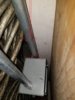
Indeed I made some progress over the weekend and used MC (Metal Clad) AWG 6 from the master panel to the Junction box.
I was also able simplify and make a nicer EMT raceway curb for the branch going toward the UMC subpanel.
So with the existing Aluminium Romex, there are now three types of wires connected to the junction box.

Main Panel to Junction Box  .jpg
 
Last edited:
What does all of your setup have to do with the OP in this threads situation?

Here is the OP initial thread.

So I got an estimate back to install a charger in my apartment building, and it came to over $8,000, which isn't feasible.
The idea had been to install an outlet in the garage underneath the apartment at my parking space,
which would have been great if it had worked, but it doesn't. I do have other options I'm already working on,
but I thought I would ask: anybody got any creative ideas for charging a Model 3 when you live in an apartment?

I hope that my current project experience was helpful.

Did you just put it in this thread because you are also wiring in an apartment?

Yes I was in a similar situation.

- How to branch out a new line form the main feed in an apartment situation has been in my thought for a long time
and made me hesitate a great deal for getting an EV, like many people do. At least I was not parking in the street.

- It's a critical point, solutions on doing it may vary depending on the situation.

Having an external junction box minimize the impact on the original system.
This can be reverse back to the original system if needed.

A cleaner solution would be to perform the junction inside the main panel.
One issue was to add an additional wire to the main panel electrical box,
while there was no preexisting knockout out hole for it.

A cheating solution was to use tandem breakers in the main panel.

Also a reliable way to perform the split is to use specifically design junction connectors,
such as Polaris IPL 4-3 as mentioned by @davewill.

And a final protection, is to use a disconnect box to protect from overloading.
 
Last edited:
Ok, Fair enough. It just seem to have devolved from a "conceptual ideas" type question to a "in the weeds nuts and bolts" type conversation which is different from where the OP was.

Not trying to throw shade, but I was also hoping the OP would update us on what the final resolution was, and concerned that the "in the weeds" detail nuts and bolts of your situation might be preventing her from doing so.
 
@NeverFollow, Did you decide against the automatic disconnect box?

This out of my control. It might be required for getting a permit inspection.

I don't particularly think you need one, but if you were to install one,
it needs to be where your junction box is now so it can monitor the draw from your apartment.

I included a disconnect box in the design and it should be installed after the subpanel,
There is a two feet EMT just above the subpanel that can be easily remove and replaced with a disconnect box.
You are right, you need to put also the current probes inside the connection box to measure the current coming from the main panel.