Welcome to Tesla Motors Club
Discuss Tesla's Model S, Model 3, Model X, Model Y, Cybertruck, Roadster and More.
Register

How-to: Changing the IEC 62196/Type 2 Charging Cable of Tesla Wall Connector

This site may earn commission on affiliate links.
First of all, please forgive me any spelling mistakes as English is a second language to me.

I want to give you my impressions on the Tesla Wall Connector and the possibility to change it's charging cable. I translated this from German. Also, I wrote more about my motivations and experiences going into this project. I can also translate this into English if you are interested. (Here is the link to my German article)


How-To

(DISCLAMER: I do not take any responsibility for this guide or any faults that may be a direct or indirect consequence of it. Also I am no electrician AND English is my second language, so please forgive me for any false terms)
This is a translated guide and the cabling is adapted to European power!

  1. TURN OFF THE POWER!
  2. Remove the old charging cable
    Unscrew the top cover of the wallbox. Also, the upper black panel has to come off. To do so, carefully insert a plastic pick under the round clip and lift it up.

    You will find the relay in the top. Unscrew the cables coming from the right and undo the ferrules as to separate the small cables to connect them to the new cord.
    IMG_1071.jpg

    Also you have to unscrew the grounding, located in the bottom of the case.

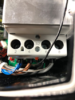
    Next, you have to unscrew the small communication cables. They have the following purpose:
    Purple: +-12V Control Pilot
    Red: +3.3V for the UHF switch, opening the Tesla-Charging Door
    Black-White: NTC temperature sensor of the charging handle
    Orange: Proximity Pilot
    IMG_1072.jpg
    '

    As a last step, the strain relief in the very bottom has to be loosened. Now you can pull the old charging cable out of the wallbox.

  3. Installing the new cord
    My third-party cord came with the following cables (Again: EU configuration, can be adapted to US)
    3 x phase, neutral, PE and CP
    The phases as well as neutral have to be connected to the corresponding smaller cables and ferruled together and screwed into the relay.
    Next, the PE has to be screwed into its original position at the bottom.

    Now we have to deal with the small communication cables. (going left to right)
    - the CP cable of the new cord is inserted into the leftmost screw terminal.
    - the next terminal on the right (3V3) is left with no cable attached
    - in case your new charging cable does not have a temperature sensor you have to replicate the signal. Because the original cord had a temperature-sensitive resistor, we can use a regular resistor with 10K Ω which resembles a temperature of 20°C/68°F. (Again, I am no electrician and can not be held accountable for this guide! Please use your temperature sensor if your cable has one). The wallbox will measure the resistance against the PE of the charging cable. Thus we will connect the 3. terminal via a 10K Ω resistor to the PE of the charging cable.
    - the last terminal on the right is the PP. One of its tasks is to tell the car how many amps the cable can deliver because of its length and resistance. This information is delivered by fixed resistance values between PP and PE (63A ≈ 100 Ω, 32A ≈ 220 Ω, 20A ≈ 680 Ω, 13A ≈ 1500 Ω/again, please double check). My new cable is able to deliver 32A, so I am connecting the 4th terminal via a 220 Ω resistor to the PE of the charging cable
    IMG_1114.jpg

  4. Moment of truth
    The diagnostic LEDs on the front cover of the wall connector are a good possibility to check for mistakes.
    You can check in the Wall Connector manual for the LED sequences. They can be replayed by holding the RESET button on the left side of the box.

    Either way, if you get the all green: Congratulations!

    I hope I could save you some time on your own project!
    Also: See the attached diagram of the circuit board of the Wall Connector as well as the one of my charging cable.


IMG_1118.jpg
 

Attachments

  • image.png
    image.png
    181.6 KB · Views: 940
  • Charging Cable 3 Phases.pdf
    1.1 MB · Views: 843
  • Tesla Wall Connector Circuit Board.pdf
    159.4 KB · Views: 716
Thank you very much for this How-To!
I just managed to successfully replace the TWC cable for a 1-phase type 1 cable. (for a Mitsubishi Outlander in this case)

The cable only had a Control Pilot wire. I first connected only that pilot wire and tried charging, got the red lighti indicating a error (probably because of the thermal sensor/NTC) After some searching I found this How-To.

Used a 10kOhm resistor between Thermal sensor and PE (ground) just like you. (I measured a 14kOhm resistance on the original cable at about 17 degrees Celsius, so that 10 kOhm sounded about right)
Used a 680ohm resistor between PP and PE (ground) because I had a 16A charging cable.

To get charging working with the Outlander (and suposedly some other cars) setting dip-switch no.2 to the down position is required. (legacy-mode)

Again: thank you!
 
- in case your new charging cable does not have a temperature sensor you have to replicate the signal. Because the original cord had a temperature-sensitive resistor, we can use a regular resistor with 10K Ω which resembles a temperature of 20°C/68°F. (Again, I am no electrician and can not be held accountable for this guide! Please use your temperature sensor if your cable has one). The wallbox will measure the resistance against the PE of the charging cable. Thus we will connect the 3. terminal via a 10K Ω resistor to the PE of the charging cable.

Let me begin to say: compliments for describing in detail how to change the cable, with clear photos.
This will be very helpful for people with a broken cable.

However, I disagree strongly with removing (spoofing) safety measures, that were installed by Tesla.
There have been mishaps because of too high temperatures in the connection with the car: the temperature sensor is a very important safety measure.
So, it would be good (to put it nicely) if you, or someone else, describes how a faulty sensor can be replaced by a functioning new sensor.
It would make your description complete and more important: safe.
 
However, I disagree strongly with removing (spoofing) safety measures, that were installed by Tesla.
There have been mishaps because of too high temperatures in the connection with the car: the temperature sensor is a very important safety measure.
Name one. You may be surprised to learn that Tesla is the ONLY maker of EVSEs that uses a temperature sensor in its Type 2 female plugs intended for domestic use. How many incidents have there been involving danger to persons caused by an overheating Type 2 female plug?

I'm afraid your attitude is responsible for the whole of the western world grinding to a halt due to hysterical over-reactions to wildly improbable and/or grossly misrepresented 'potentially dangerous eventualities' by a health and safety culture gone mad (the world's reaction to Covid19 being another example). In short, there is no longer any sense of reasonable and logically formulated proportionality.
 
  • Disagree
Reactions: Rocky_H
Name one. You may be surprised to learn that Tesla is the ONLY maker of EVSEs that uses a temperature sensor in its Type 2 female plugs intended for domestic use. How many incidents have there been involving danger to persons caused by an overheating Type 2 female plug?

I'm afraid your attitude is responsible for the whole of the western world grinding to a halt due to hysterical over-reactions to wildly improbable and/or grossly misrepresented 'potentially dangerous eventualities' by a health and safety culture gone mad (the world's reaction to Covid19 being another example). In short, there is no longer any sense of reasonable and logically formulated proportionality.
It’s not every day we get an electrical safety AND public health expert on these boards!

Cheers to you, mate. Thanks for setting us all straight.
 
However, I disagree strongly with removing (spoofing) safety measures, that were installed by Tesla.
There have been mishaps because of too high temperatures in the connection with the car: the temperature sensor is a very important safety measure.
Name one.
How about a lot more than just one, pal?


You may be surprised to learn that Tesla is the ONLY maker of EVSEs that uses a temperature sensor in its Type 2 female plugs intended for domestic use. How many incidents have there been involving danger to persons caused by an overheating Type 2 female plug?
Ah, I see you missed the point and didn't realize this topic was something else entirely. This was not about Type 2 cables at public charging stations. This was about receptacle plug adapters using the universal mobile charging cable that plugs into house electrical receptacles.
 
  • Helpful
Reactions: Maarten