Welcome to Tesla Motors Club
Discuss Tesla's Model S, Model 3, Model X, Model Y, Cybertruck, Roadster and More.
Register

Mobile charger with single phase 240v circuit ground loss

This site may earn commission on affiliate links.
Not surprised it's not working. L1 or L2 is not supposed to be bounded to ground. In the US, L1 and L2 is 120V vs N (which generally is same potential as G). L1 vs L2 is 240V. In Australia from what I can find, L1 and L2 is 240V vs N.

Note the Tesla UMC when using 240V doesn't even use the neutral at all, so I don't think it cares at all if you have split phase, just that your setup is properly grounded. Have you tried using the UMC on an actual 240V circuit powered by the grid? That would confirm if it's working fine with the 240V setup in your country.

I think your issue is your inverter is either not grounded properly or it was not designed to be grounded in the first place (but rather floating), in which case it's not compatible with EV charging that relies on a ground for protection against electrocution (which is why the later a EVSE you bought doesn't work either).

The UMC works fine when tested with 240v split phase grid power (balanced legs). I know it doesn't need neutral for 240v. With single phase 240v I was able to bypass the ground check by bonding L2 to ground, so the grounding issue is solved. However, since L1 and L2 are out of balance (~90v / ~150v), the UMC can't detect the outlet properly and caps at 8A. It charges fine at 8A.

The solution should be an auto transformer to balance the legs.
 
The UMC works fine when tested with 240v split phase grid power (balanced legs).
I thought you were in a country without a split phase, from the previous posts, but if not I guess you can't really test the condition where both L1 and L2 are 240V to N.
I know it doesn't need neutral for 240v. With single phase 240v I was able to bypass the ground check by bonding L2 to ground, so the grounding issue is solved. However, since L1 and L2 are out of balance (~90v / ~150v), the UMC can't detect the outlet properly and caps at 8A. It charges fine at 8A.
That doesn't make sense. Given you have bonded L2 to ground, isn't L2 is now at 0V to ground and L1 is 240V to ground? The issue is your L2 is now at ground, which the UMC obviously does not like.

The out of balance would only be apparent if neither L1 nor L2 is bonded to ground.

If you have a gen 2 UMC, the connector detection uses an embedded chip in the adapter, which should not be affected by the power connections.

The gen 1 UMC uses resistance values, which might be affected.

The solution should be an auto transformer to balance the legs.
 
  • Like
Reactions: Rocky_H
I thought you were in a country without a split phase, from the previous posts, but if not I guess you can't really test the condition where both L1 and L2 are 240V to N.

That doesn't make sense. Given you have bonded L2 to ground, isn't L2 is now at 0V to ground and L1 is 240V to ground? The issue is your L2 is now at ground, which the UMC obviously does not like.

The out of balance would only be apparent if neither L1 nor L2 is bonded to ground.

If you have a gen 2 UMC, the connector detection uses an embedded chip in the adapter, which should not be affected by the power connections.

The gen 1 UMC uses resistance values, which might be affected.

The 240v AC outputs on my inverter are L1, L2, and G. Measuring L1 to L2 is ~240v. Without bonding either L1 or L2 to G (tied to 8 foot copper ground rod), L1 to G is ~90v, and L2 to G is ~150v. Apparently this is common for single phase.

Without either L1 or L2 bonded to G, the gen 2 UMC threw a ground loss error (blank "ESLA" with 2 x flashing red "T"). Bonding L2 to G got rid of the ground loss error but then threw an outlet detection error (green "ESLA" with 5 x flashing red "T"). My assumption is due to unbalanced legs. This caps charging to 8A, but charging at 8A works fine.

The good news is that my 5000w two way 120v/240v step up/down transformer gives me ~120v output on both L1 to G and L2 to G when hung off one of my 5000w 120v inverters, so I'm going to wire up a 14-50 to the output and test this weekend. I'll be satisfied with ~4500w charging, as I really don't want to drop $800 on a Victron auto transformer to clean up the 240v.
 
That's usually an adapter not fully plugged into the UMC, and might not have anything to do with the power quality/type.

It's not the adapter. This is a brand new UMC and I also tested back and forth from off grid 14-50 outlet to on grid 14-50 outlet several times and each time it threw the error only on the off grid outlet. It also throws the error with my 6-50 adapter / off grid outlet. The 5-15 adapter is fine both off grid and on grid. It doesn't like the 240v circuit. The Chinesium charger also only works on grid and won't charge at all with the off grid circuit.
 
The 240v AC outputs on my inverter are L1, L2, and G. Measuring L1 to L2 is ~240v. Without bonding either L1 or L2 to G (tied to 8 foot copper ground rod), L1 to G is ~90v, and L2 to G is ~150v. Apparently this is common for single phase.

Without either L1 or L2 bonded to G, the gen 2 UMC threw a ground loss error (blank "ESLA" with 2 x flashing red "T").
I'm saying the issue with this configuration is likely an issue with your ground bonding on your inverter (or any of your connections, including your outlet), not necessarily the imbalance.
Bonding L2 to G got rid of the ground loss error but then threw an outlet detection error (green "ESLA" with 5 x flashing red "T"). My assumption is due to unbalanced legs. This caps charging to 8A, but charging at 8A works fine.
My point is in the second configuration, your legs are no longer "unbalanced" given if you measure L2 to G you would get 0V, and L1 to G you would get 240V. There would no longer be the ~90V or ~150V you measured. So the 8A limit is not from imbalance.
The good news is that my 5000w two way 120v/240v step up/down transformer gives me ~120v output on both L1 to G and L2 to G when hung off one of my 5000w 120v inverters, so I'm going to wire up a 14-50 to the output and test this weekend. I'll be satisfied with ~4500w charging, as I really don't want to drop $800 on a Victron auto transformer to clean up the 240v.
 
  • Like
Reactions: Rocky_H
At this point I'm fairly convinced that the UMC needs a split phase system with neutral / ground bonded in order to pass the ground check.
It's certainly not that, because the Neutral pins in the Tesla plugs in the ones like 14-30 or 14-50 are literally just dummy pieces of metal. They don't even have an internal wire connected to them. And people charge from 240V only outlet types like 6-50, 6-30 or 6-20 just fine. Those are just three wire, with Hot1, Hot2, and ground. There's no neutral there. And the UMC manages to test the ground connection somehow with those and pass. I still think there is something a little funny with the ground and/or how it is tested. The testing procedure would have to take a little current from one of the hot lines, and since yours are strangely severely imbalanced with 90 and 150 volts, I don't know if that is somehow confusing the UMC as it tries to run that ground test.
 
I've pretty much confirmed that the issue is related to unbalanced legs native to single phase 240v. Although the UMC doesn't use the neutral line, it wants balanced legs (as does the Chinesium charger).

Both the UMC and Chinesium chargers work beautifully with my $200 5000w 120v to 240v step up transformer hanging off my 5000w 120v solar inverter. I'm able to squeeze about 4000w at 240v out of the inverter through the transfomer, which translates to about 16a @ ~222v going into the Tesla (pretty substantial voltage drop). Pushing it past 16a trips the breaker on the transformer (it pulled 18a for about a minute).

I'm happy that I don't have to drop $800 on an auto transformer right now, but it's on my Christmas wish list.

Thanks again for everyone's input - I've learned a lot and I only shocked myself once throughout this process!
 
@Baked Billy -

I use an OpenEVSE hooked to a pair of Growatts making split phase, but no neutral is provided to the OpenEVSE so it can't tell the difference between split phase and single phase. It does want a proper ground if you have the GFCI test turned on. But other than that, give it ~120V or give it ~240V across L1 to L2 pins of the 14-X plug and it seems to be happy. I haven't thrown imbalanced legs at it, so I cannot say for sure that won't trip up an OpenEVSE, but I don't think so. Chris, the owner of the store who also answers the tech support option might know. But I'd recommend you give the OpenEVSE a shot...

I'm hardly an electrician and my terminology is usually incorrect, but when I use the term "unbalanced legs" I mean something is off with the phase / freq / modulation.

Signature Solar sells both Victron and Growatt devices to clean up the single phase 240v to provide two inverted 120v legs. I'm sure either of these devices would fix the issue with my single phase 240v inverter. DavidPoz and OffGrid garage have videos discussing the issue.

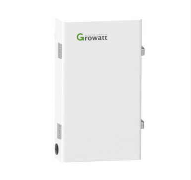
Here is the description of the Growatt device:

"The ATS 5000T-ES transformer takes Single Phase 240Vac (L/N) electricity output and creates true Split Phase 120Vac/120Vac (L/L/N). This addition to our line sheet increases the user's safety and ease of use with designated input and output locations to simplify connecting this transformer to your system. Perfect for use with the Growatt 5kW ES off-grid inverter"

Here is the Victron description:

"Victron Energy Autotransformer can be used for step up, step down and split phase output balancing purposes"
"While the step up and step down functions are fairly straightforward, split phase output balancing may require some more attention"
"An alternative to stacked inverters: The alternative to stacking two 120V inverters to provide a 120/240V split phase supply is a 240V inverter with an additional Autotransformer"
 
I know that I'm a little late to this thread, however i had the same issues and questions to see if we could get the UMC working from an Inverter in an off grid scenario using a single phase 240V pure sinewave output.

Since the output of the inverter is a single phase (Not split), i created the ground bond and the UMC fired up just fine (No flashing "T" on the UMC). Plugged it into the Model Y and the car recognized 220-240'ish volts but didn't energize the car relays for charging, but the UMC relays were clicking on, but the car didn't start charging. Eventually said a comms error.

I plugged the UMC into a 240 Supply in my home and a 110v supply in my home and the UMC worked fine. charging the car and all worked great. It was a relief to know the car and the charger were all still good!

Investigated the split system converter from a single phase ended up being around $2K so not going that that route yet.

I've seen the Victron synchronized split phase inverters 240 made from 2x120V inverters and then a ground rod. Seems cool, but the cost is very high.

I'm guessing from all of the conversations here no one has actually figured out how to run the UMC from a solar single phase 240V system yet?
 
Actually found this - looks like a simple 240 Single to L1 and L2 Transformer little over 11KW.

 
Actually found this - looks like a simple 240 Single to L1 and L2 Transformer little over 11KW.

That is an auto transformer and creates a 120V midpoint from a 240V feed. It doesn't fix the issue of the 240V being referenced to ground.
 
referenced to ground.
But does the car/charger even know what 'ground' is? All it sees is three wires, and with luck the middle one is a steady midpoint of the other two. Even in a split phase 240 system the ground may not be absolutely perfect(hopefully it is). In theory, the transformer referenced would provide a very steady center point.

Side note... if you don't mind a little wasted power, two evenly matched RESISTORS would get you the same midpoint(!). The problem is that they might have to be pretty hefty(power wasting) to get a good steady midpoint. Lets suppose for a moment you didn't mind throwing 24W to the wind., you'd want resistors (240*240)/24 divided by 2(since they'd be in series), aka 1200 ohm 12 watt resistors. You'd definitely want them to be much more power-rated than what you expect(the minimum 12W), because they will be very heated all the time.

www.amazon.com/LM-YN-Wirewound-Electronic-Industrial/dp/B076WM87M5 is a pair of 1000w resistors that would dissipate 28.8W continuously(combined) when placed in series across a 240V source. The midpoint would be relatively solid. If you wanted, you could even get two pairs and put them all in series, and the total dissipation would drop to 14.4W, each resistor only emanating 3.6W of its 50W max, probably barely warm to the touch. The problem as you get to higher resistances is that the midpoint will become easier and easier to push around, and I'm not sure at what point the UMC will start to get suspicious that it doesn't have a good ground. Still, wagering $10-$20 is better than $500.

TBH, once you are over 3kohm on each side of the midpoint, the current(and therefore dissipation) will have dropped enough to make 5W resistors like www.amazon.com/uxcell-Tolerance-Resistance-Electronic-Experiments/dp/B07RWQ2MQG/ an option.

Note that I'm not sure I'd try any of the above(aka resistor based voltage dividers) beyond an 'experiment' stage, just to see if the UMC would work. That said, at two 10kohm in series the system would only be dumping 2.88W. or 1.44W per resistor, again barely warming it. If the UMC was still happy with that, I might make it a permanent solution.
The UMC does need a ground reference, that's why minimum is three conductors, not only two. The use is for the built in GFCI to pop in case you somehow have a break in the charging cable or connector to the car, which might electrocute you otherwise.
 
  • Like
Reactions: Rocky_H
But does the car/charger even know what 'ground' is? All it sees is three wires, and with luck the middle one is a steady midpoint of the other two
Yes it does because ground is one of the three power connections to the car.

I'm just trying to get OP's UMC to work, not to keep him/her from getting electrocuted :)
Right and the issue is that some combination of the car and charger wants to see 120VAC on the two line inputs, not 240VAC and 0VAC. A true 240:240CT transformer would allow a ground referenced split phase type waveform whereas using the referenced auto transformer would not.
 
  • Disagree
Reactions: Rocky_H
Yes it does because ground is one of the three power connections to the car.


Right and the issue is that some combination of the car and charger wants to see 120VAC on the two line inputs, not 240VAC and 0VAC. A true 240:240CT transformer would allow a ground referenced split phase type waveform whereas using the referenced auto transformer would not.

I am surprised as to why it needs a split phase. Unless the UMC is different internally or there's something in the adapters, it should work in a 240-0 scenario (think Europe/South Korea). People have brought their cars overseas and L2 charging definitely works.

Funny enough I remember somewhere here getting 277V working on an older UMC, so wonder if that would work as well (Info from Tesla - 277v feed to Wall Connector (HPWC) - Which Cars Support It)

Yeah, Europe is single phase or three phase, I'm guessing it's a US UMC software limit. Peak voltage at 240VAC is still less than 400VDC so the vehicle seems like it would be fine.
From that thread:
Note that the Tesla Wall Connector is almost always hooked to center tapped 240v or 208v. The one exception is 277v where it is L-N. There is a dip switch in the Wall Connector they tell you to throw which I wonder if that puts it into a mode where it only tests for potential between Line and ground instead of testing for potential between both Lines and ground?
 
Yeah, Europe is single phase or three phase, I'm guessing it's a US UMC software limit. Peak voltage at 240VAC is still less than 400VDC so the vehicle seems like it would be fine.
From that thread:
The post I linked to the person used an older Gen1 mobile connector and wired it to 277V. As far as I know no dip switches or soldering was done in that UMC, just made a custom pigtail to hook it up, so no dip switch involved.

Getting an older UMC might work, one could also try to wire an older Gen2 HPWC and use that dip switch to see if it would work; in general the HPWC should work if they're identical to the ones use in SK (the only other place I know of that has 240 L/N and also NACS).

I'm also not 100% convinced there's something different about the UMC; I am pretty sure if you took an euro plug adapter and put it into the american UMC and charged overseas it would work (could be wrong of course).

edit: the person tested with a Gen 2 UMC and it just worked, so I don't think the 240->0 L/N is the issue. Info from Tesla - 277v feed to Wall Connector (HPWC) - Which Cars Support It