Still waiting to pick up my car but I just got a 14-50 socket installed today and when i plug in the MC, the T flashes 2x, indicating a "ground loss". I measured the voltage across L1-to-ground, L2-to-ground, L1-to-neutral, and L2-to-neutral - they all read ~120V so no issues there. I looked at the ground and neutral to the buses at the panel and they're all tight. When i plug the MC to a 5-15 outlet, it's all green, so don't think it's the MC problem.
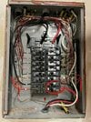
Attached a pic of the subpanel. The bottom right 50amp is the MC breaker. Also circled in red are the ground and neutral wire to their respective bus connection.
Any thoughts any one?
Attached a pic of the subpanel. The bottom right 50amp is the MC breaker. Also circled in red are the ground and neutral wire to their respective bus connection.
Any thoughts any one?