Welcome to Tesla Motors Club
Discuss Tesla's Model S, Model 3, Model X, Model Y, Cybertruck, Roadster and More.
Register

Model 3 Power Liftgate?

This site may earn commission on affiliate links.
@Fernand,
It says that’s a 10 MM ball. Is that the same size as the plastic ball joint you replaced? Also does it snap on /off any easier/more difficult that the original. Does it seem more secure to you, ie. to prevent failure.
Ski

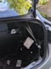
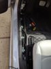
You unscrew the plastic one and the metal one screws on instead. It's a simple replacement. It snaps on with a feel that's a lot like the plastic one when new, if you look at the 1st photo above you can see there's a retaining internal clip. But then you also insert a pin that blocks the socket from coming off the ball and that clips around the neck, look at the second photo, it's very secure. People use them on trailer doors etc.

I don't yet know what the alloy is, if there's any chance of cracking over the centuries, but it's not going to wear like the plastic, and that pin locks it on. I don't think it's going anywhere like in @Garlan Garner's case. I don't believe the bottom one is as much of an exposure, As Garlan pointed out, it doesn't move much during the cycle so it's not subject to as much wear. But if someone was very worried, that one could be upgraded to metal too.

These add $14 to the i1Tesla Frunk-Trunk project, still under $80 total.
It's quick and easy to install, but of course the trunk doesn't auto-close.

If someone finds a cheaper source, let us know. I got mine here
https://www.amazon.com/gp/product/B...sin_title_o00_s00?ie=UTF8&psc=1&tag=tmc064-20

20190510_192703Lx.jpg
 
Last edited:
  • Informative
Reactions: NCDoc and KenC
Installation update #1 - CAN wire & Driver side switch.
Couldn’t do the install over the weekend. My daughter’s birthday and of course Mother’s Day. I would have been crucified if I spent time with the car.
I only had a couple of hours for today’s install. Had homework duty and dinner.
So I decided to make sure my CAN wires match with what they had in their instructions. If not, it would have been game over. Luckily they matched.
63F1E463-0E99-463D-A398-316B9850230E.jpeg

HINT: while inside the car, close the door and mark where you want to install the switch.
It was pretty easy removing the panels to get to the CAN wires.
Make sure you have a plastic pry tool to make the job easier.
C8E6F7E2-5EDF-45C9-A227-A50C847FB101.jpeg

HINT: I zip tied the CAN wires and Trunk Control Button Cables together since they both will be running on the driver side panels.

I ran both wires starting from the front of the car and made my way to the rear. It was an easy process. I just followed the video they posted.

Next was tapping the CAN wires. Just tripled check their instructions with my wires before tapping. I had to use pliers to crimp the t connectors together.
F01C312C-E6E5-491C-9C16-017EC7F1C0DB.jpeg

Next up was to install the switch to the panel. Used the provided drill bit and drilled away.
5C556A4C-AFA5-47FC-9D35-457FEBC45864.jpeg

Finally, connect the switch to the wire and put all the panels back.
554F0BE6-40D4-46CB-8DDB-00C29B30309F.jpeg

Done for now..
 
Installation update #2 - Foot Sensor (optional component)
Bumper removal was easy since it’s my second time around. First time was when I installed the hitch. Their bumper removal instructions/video should suffice.

DC1BC9E6-AF24-4832-9E5E-B7687D4BD82E.jpeg

I decided to take a shortcut and not remove the bolts under the center of the car. Unfortunately, I didn’t realize that the clips at the ends of the bumper were scratching my fender paint.
SO REMEMBER TO TAPE THE CLIPS IF YOU PLAN ON DROPPING THE BUMPER WITHOUT COMPLETELY REMOVING ALL THE BOLTS. Safe bet is to completely remove the bumper.

7DEAF7ED-4F08-48D1-B020-D42DF9A26B82.jpeg

Placed the sensor on the left side of my hitch opening and ran the wires to the right side of the rear fender.

79922B47-E0AB-4175-B4CA-059E702BA124.jpeg

AFD92BAB-3F9B-4E56-B4F9-EF2F25E45830.jpeg

I encountered an issue when reinstalling the bumper. It wouldn’t fit right. Turns out, one of the bumper wire harness got loose from the bumper and was getting in the way.
So make sure the wire harnesses are attached to where they’re supposed to be.

That’s it for now.
 
My install is complete. I just finished.too tired to write much but took 5 hours and works as advertised
 

Attachments

  • IMG_20190515_184128.jpg
    IMG_20190515_184128.jpg
    471.9 KB · Views: 335
  • IMG_20190515_163838.jpg
    IMG_20190515_163838.jpg
    480.7 KB · Views: 326
  • IMG_20190515_163835.jpg
    IMG_20190515_163835.jpg
    511.5 KB · Views: 339
  • IMG_20190515_163914.jpg
    IMG_20190515_163914.jpg
    404.2 KB · Views: 325
  • IMG_20190510_190824.jpg
    IMG_20190510_190824.jpg
    355.1 KB · Views: 319
  • IMG_20190510_184804.jpg
    IMG_20190510_184804.jpg
    598.1 KB · Views: 324
Installation Update #3 - finished

Lift gate wires - you will be running 2 wire harnesses to the lift gate area (3 if you have the foot sensor).
HINT: The foot sensor required you to run a green wire up to the lift gate area. Instead of tapping at the lift gate area, tap the same wire closer to the control box.
0FFFB5E7-A3A3-4081-A94A-16EB942F36B5.jpeg

HINT: run the bigger connector through the hole first or else you won’t be able to squeeze the bigger connector if the smaller one is already through the hole.
43D66A59-6507-47B5-A6A7-CAD263C38B1B.jpeg

There was no way I could route the wire harnesses inside the rubber housing. So I made a hole through it and zip tied it to the housing.
E2FDE7BE-0550-42D2-A3DE-054F7EDF8A8B.jpeg B6295325-7861-41A7-8E65-A23D60B5D09F.jpeg

I ran the strut wires behind the tail lights.
06E19962-2CEF-4794-A72E-3A3E77866FB1.jpeg

Ran the power wire per their instructions.
B7D5FEDD-14DD-42B1-8FCA-0B0A881C4B67.jpeg

When I removed the lift gate panel, 90% of the fasteners dislodged from the panel and remained on the lift gate. I suggest you get a strong pry tool to get the fasteners out of the lift gate.
267ACE3C-FC07-4B8F-B632-614060935EA1.jpeg

Attached the beeper speaker.
4EE995B3-8A1C-4079-88CB-4C1D360E72C2.jpeg

Connect everything. Stuffed it by the subwoofer compartment.
6440AA31-CC36-4099-9582-074118F97C59.jpeg EB4EF048-DB87-4858-A75E-BA7BEDE09AE8.jpeg

Done
 
Am I correct in assuming that one missing feature on this aftermarket kit is any kind of safety stop? Don't most OEM auto closing trunks have both a slow closing mechanism that cinches via the latch and a torque sensor that would prevent a limb from getting closed in? This kit appears to just slam shut the last 25%? Just curious about the safety.
 
Peoples' Liberation Army don't worry about limbs.
Sorry, just kidding. That's very cool, @Twincam23.
and you too @Lee_B. Congratulations on clean installs, dudes!

Twin, I see you got the black retro plates, too. Those of us
who went with cost-effective basic black are really really happy
with those. I took the frame off, it's like the yellow lettering appears
right on the car body. I even enjoy closing the trunk manually for that ;-)
 
Last edited:
Am I correct in assuming that one missing feature on this aftermarket kit is any kind of safety stop? Don't most OEM auto closing trunks have both a slow closing mechanism that cinches via the latch and a torque sensor that would prevent a limb from getting closed in? This kit appears to just slam shut the last 25%? Just curious about the safety.

There’s pinch prevention. I have the speed set to 6 which is the fastest when opening and closing the gate.

 
  • Helpful
Reactions: NCDoc
I fitted my 3 with the actuators from Teslaoffer today. Here's Few tips for anyone attempting this, since the install guide really is a bit vague with quite a few steps missing:

  • When wiring the lift gate harness through the rubber flex pipe, make sure to also wire the trunk release button harness at the same time through the rubber pipe.
    • I removed the connectors from both harnesses to make it easier to get through the rubber flex pipe, and then re-assembled them once through.
    • Use plenty of cable lube when pulling the wires
    • Don't forget to re-secure the flex pipe before testing.
      • I didn't, and it got trapped and nearly sliced through it. (oops) It also jammed shut and I had to use the manual release to open it.
    • Also cutting and splicing the wires back together can also work, since removing the connectors is a bit of pain. There is also a bit of excess wire, so this might be tidier.
  • On the step for wiring the Canbus wires on the left side of the car, make sure to run the trunk release button harness at the same time.
  • I used method 2 for the actuator wires (through the rear tail lights), since this routes the wires better than method, 1 and is quicker and easier.
  • Didn't do the foot sensor, since it was out of stock when I ordered. I assume this can be retrofitted if it's sold separately.
 
  • Helpful
  • Like
Reactions: NCDoc and MP3Mike
I fitted my 3 with the actuators from Teslaoffer today. Here's Few tips for anyone attempting this, since the install guide really is a bit vague with quite a few steps missing:

  • When wiring the lift gate harness through the rubber flex pipe, make sure to also wire the trunk release button harness at the same time through the rubber pipe.
    • I removed the connectors from both harnesses to make it easier to get through the rubber flex pipe, and then re-assembled them once through.
    • Use plenty of cable lube when pulling the wires
    • Don't forget to re-secure the flex pipe before testing.
      • I didn't, and it got trapped and nearly sliced through it. (oops) It also jammed shut and I had to use the manual release to open it.
    • Also cutting and splicing the wires back together can also work, since removing the connectors is a bit of pain. There is also a bit of excess wire, so this might be tidier.
  • On the step for wiring the Canbus wires on the left side of the car, make sure to run the trunk release button harness at the same time.
  • I used method 2 for the actuator wires (through the rear tail lights), since this routes the wires better than method, 1 and is quicker and easier.
  • Didn't do the foot sensor, since it was out of stock when I ordered. I assume this can be retrofitted if it's sold separately.
How long would you estimate the installation took you?
 
@insaneoctane
About 8 hours, but I wasted a ton of time trying to get the harness through the rubber tube and then had to waste time with the second harness when it would’ve been easier to do together. Same sort of deal with the front switch.

I could likely do it in about 4 or 5 hours for a second attempt. With more practice its maybe a 3 hour job for somebody competent.
 
  • Like
Reactions: MP3Mike
For those that have installed already.......does this open to the same height as the OEM struts? In some vids it looks shorter. Like some height is lost? I do realize the height is somewhat setting adjustable. Just curious as to the max open height.

Ski