Welcome to Tesla Motors Club
Discuss Tesla's Model S, Model 3, Model X, Model Y, Cybertruck, Roadster and More.
Register

Questions about detached garage

This site may earn commission on affiliate links.

user212_nr

Active Member
Aug 26, 2019
1,407
887
US
Hi,

I have some questions about installing "Level 2" charging for a Model 3 Standard Range Plus in a detached garage. The garage is 52 feet from the house, with existing 110v lines (2 overhead wires to the house) and old breaker box. There is an additional 50-70 feet from where the wires meet the house from the garage, to where the wires connect to the house from the street. House was built in 1952 initially, so the garage would have been built and electrified sometime after that.

I have many questions, so I'll group them into categories. My main goal is to get faster charging installed at the lowest cost (in case I decide to move, and the house is not mine to benefit from improvements), and also to fill in some gaps about my electrical knowledge. I assume that this would be done by not supplying 220v service to the garage, but using existing lines. Can call an electrician, but want to be informed beforehand.

If you only want / are able to answer some questions, that is fine.

Questions about 110v/220v
1. If a house has 220v service (ie. for a drier outlet), then the 220v is supplied via separate wire from the street. We have 2 electric wires from the street and a 220v drier socket, so one would be 110 and the other 220?
2. Using a transformer to go from 220v to 110v or vice versa is not a thing people do inside their homes or garage. For example, lets say the wires for the garage were converted from 110v to 220, then it would double the watts, but then there would be no way to get 110v service, except via a transformer. I don't know - is that a reasonable thing to supply 220v to garage via existing lines and then step it down?

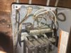
Questions about existing wiring
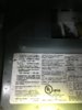
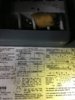
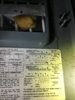
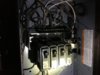
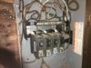
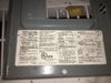
1. The garage has its own circuit breaker, with 4 breaker toggles 20 amps each (total 80 amps. It says on the panel "max 100 amps with 80% average current". So that means that, if dedicated only to charging a Tesla (a fair assumption generally), that it could supply 80 amps at 110v?

Questions about Tesla UMC and Wall Charger
1. Can the Tesla mobile charger take, instead of 32 amps on 220v, 64 amps on a 110v socket (assuming that the electrician wired such a socket)?
2. There is the setting inside of the car to select how many amps the UMC will draw. At first it said 32 amps, but then when plugged in, it correctly went down to 12. How does it determine that? If I use the UMC to charge at 64 amps 110v (assuming that is possible), then would it try to draw that when plugged in elsewhere?
3. Can the Tesla wall connector do 64 amps at 100v?

I think I've figured it out, that what I need is to do either the UMC or the Wall Connector at 64 amps 110v, having an electrician install that, but want to check my sanity.
 
Your house is fed 240V on 3 wires, neutral, and two 120V line wires that are 180 degrees out of phase. So Line to Neutral is 120V and Line to Line is 240V. Probably, you would replace your current run with a new 3 or 4 (with ground) wire 240V branch circuit run to the garage to a new panel there. THat would feed the vehicle connector and your other garage loads (120V and 240V).

Your max current is a lower number than the sum of your circuit breakers.

The wall unit is a connector not a charger. The charger is built into the car.
The UMC determines max current by the adapter you use. The Wall connector has an internal switch that is set at installation time for the circuit capacity.
The charger cannot do 64 Amps.
 
...1. If a house has 220v service (ie. for a drier outlet), then the 220v is supplied via separate wire from the street. We have 2 electric wires from the street and a 220v drier socket, so one would be 110 and the other 220?...

As @mongo explained, you don't need any transformer / voltage converter for your 120 / 240V system. They are already there in the 3 wires coming from your utility company for an electrician to pick and choose.

...instead of 32 amps on 220v, 64 amps on a 110v socket (assuming that the electrician wired such a socket)?...

Most 120V outlets are rated for 15A

gp-sere01asw_0.jpg


and newer ones are rated 20A to also accommodate the horizontal blade on the left below:

HOM-PSHREC20W_1.jpg


That's the maximum that your UMC can work with your 120V line.
 
2. Using a transformer to go from 220v to 110v or vice versa is not a thing people do inside their homes or garage. For example, lets say the wires for the garage were converted from 110v to 220, then it would double the watts, but then there would be no way to get 110v service, except via a transformer. I don't know - is that a reasonable thing to supply 220v to garage via existing lines and then step it down?

No you can’t get free power :)

Watts is a measure of power, a transformer that doubles the voltage will cut the current in half, giving you the same power (minus losses). Power is voltage (V) x current (A).

That said, if you have 120V, 80A available to you in the garage, you COULD install a boost transformer to get roughly 240V, 40A.

If you fed that into a wall connector you’d be charging at 9.6 kW.
The max you can charge with the mobile connector is 32 A, so 120 x 32 = 3.8 kW, or 240 x 32 = 7.7 kW.
To charge at 32 A continuous you need a circuit that’s 40 A.

You should get an electrician to check the panel in the garage, if it has the full 240V input then you don’t need to consider a transformer at all.
The max he can charge a standard plus is at 32A.
 
  • Like
Reactions: darth_vad3r
I'm going to start by noting that the correct voltages are 120v and 240v. 110 and 220 haven't been used in decades.

I find myself a little confused by your descriptions. If there are 4 separate breakers for the garage, it seems likely that there is already 240v going to your garage...although your description of only 2 wires going to the garage does argue against that. If that's so, and you don't have much out there in the way of electrical loads, it's possible you could squeeze a 240v 20a circuit out of the existing wiring by moving the existing 120v circuits onto two of the breakers...but I'm not comfortable actually recommending something like that based on the info we have. A 240v 20a circuit would charge your car almost three times faster than a standard 120v 15a outlet.

Tesla only provides 120v adapters for up to 20a (16a charging), although some people here have made their own and used the Gen1 mobile connector up to 30a (24a charging). In your case, it sounds like the most you could hope for with your existing wiring at 120v is 20a.

If you want to take some pictures of what you have, we might be able to provide more clarity, which would help you to decide what you even want to ask an electrician to do.
 
Thanks all, for answers. Looks like UMC supports just NEMA 5-15 and 14-50, but this is interesting, that some say I might have 240 already. I'll attach the photos I just took (breakers are awful and obviously will need replacing). Two wires coming from the house and entering via a pipe. Looks like the wall connector supports 120v and 80amps, so that would be enough if I have it (I think).

Photos:
 

Attachments

  • IMG_0092.JPG
    IMG_0092.JPG
    464.6 KB · Views: 177
  • IMG_0093.JPG
    IMG_0093.JPG
    501 KB · Views: 118
  • IMG_0094.JPG
    IMG_0094.JPG
    452.4 KB · Views: 116
  • IMG_0095.JPG
    IMG_0095.JPG
    387.7 KB · Views: 129
  • IMG_0096.JPG
    IMG_0096.JPG
    585.8 KB · Views: 151
  • IMG_0097.JPG
    IMG_0097.JPG
    495.9 KB · Views: 127
  • IMG_0098.JPG
    IMG_0098.JPG
    565.5 KB · Views: 127
Thanks all, for answers. Looks like UMC supports just NEMA 5-15 and 14-50, but this is interesting, that some say I might have 240 already. I'll attach the photos I just took (breakers are awful and obviously will need replacing). Two wires coming from the house and entering via a pipe. Looks like the wall connector supports 120v and 80amps, so that would be enough if I have it (I think).

Photos:
Your panel is very unsafe. The feed wires are woefully undersized. It also looks to be missing an earth ground.

There are other adapters for UMC.
 
Wiring on older homes is not something to mess around with. This is all likely done by an amateur and not done correctly. For it to be safe,some money will need to be spent, sorry. A light load might be OK for a few minutes, but not car charging.

At the very least an electrician will replace the box and install a proper ground rod (likely two of them). They will likely insist on replacing the wire from the house. If the overhead wire is too close to the ground, it will need to be buried instead., which will need to be a deep trench and in conduit.

The box that the wire is feeding from inside the house is likely not in any better shape.

In short, you are talking about thousands of dollars. If it is not your house, I'd move.
 
  • Love
Reactions: Rocky_H
Looks to me like 4 wires are entering from the rear of the panel, two black (hots), one white (neutral), and one green (ground). Could be 8AWG or 6AWG, which would be consistent with 240v 40a feeding the panel and the four 20a breakers, but I'm finding it really hard to tell. Does anybody else see it differently? The pics are not all that clear.

There are plenty of different adapters available for the mobile connector:

Gen 2 NEMA Adapters
1099345-00-C_0.jpg
 
  • Helpful
Reactions: Rocky_H
Looks to me like 4 wires are entering from the rear of the panel, two black (hots), one white (neutral), and one green (ground). Could be 8AWG or 6AWG, which would be consistent with 240v 40a feeding the panel and the four 20a breakers, but I'm finding it really hard to tell. Does anybody else see it differently? The pics are not all that clear.

There are plenty of different adapters available for the mobile connector:

Gen 2 NEMA Adapters
1099345-00-C_0.jpg
Looks like 12 (maybe 10) gauge feed. The lugs are rated for 8 minimum and are barely engaging it.
SmartSelect_20190826-203233_Firefox.jpg
SmartSelect_20190826-203349_Firefox.jpg


Neutral lug has too many wires and one is discolored.
SmartSelect_20190826-203651_Firefox.jpg


If it is a four wire feed, neutral and ground should be seperate.
 
  • Like
Reactions: davewill
So I took another look at the sub-panel box, and there are 5 wires coming from the outside - 2 black wires, 2 white wires, and a red wire. One of the white wires has black tape on it towards the end, and the red wire is mostly covered in green tape (in the photo, you can see a very small bit of red where it enters the box). The two white wires are basically connected to the same place, and the red wire is close by (not clear if it is connected to the white wires).

I'm a bit confused as to what these wires are, especially as there are two identically looking overhead wires coming from the house, and an odd number of wires. The wires all say "12 AWG"

Some posters have stated that it is missing a ground wire - so maybe there are 2 black and 2 white both live that could be used to make 240v, and then the 12 gauge copper wire, when they are duplicates, could get 70 amps? That doesn't account for the red/green wire of course.
Likely some of those wires are not incoming power, but feeding some other box or breaker.

I take back what I said about the work not being done by a professional -- clearly it was. Unfortunately it was a plumber, not an electrician.;)
 
  • Funny
Reactions: Rocky_H
I've realized that there are only 2 live wires, and the rest are all ground/neutral or do nothing. I've found one 20A breaker at the house that trips the socket I'm using, and I'm guessing there is another and it is 240V 40A. That should work for a NEMA 6-20 socket, which would be "good enough". If that is the case, then its just a question of what all those "ground/neutral" wires do, and if it needs or would better have installed its own ground rod.
 
I've realized that there are only 2 live wires, and the rest are all ground/neutral or do nothing. I've found one 20A breaker at the house that trips the socket I'm using, and I'm guessing there is another and it is 240V 40A. That should work for a NEMA 6-20 socket, which would be "good enough". If that is the case, then its just a question of what all those "ground/neutral" wires do, and if it needs or would better have installed its own ground rod.
The garage should be fed by one dual pole (240V) breaker.
Each structure per NEC must have its own ground rod. The wrapped in green tape wire might go to one, but that is not the right way to do it. The breaker panel itself is not up to code either, so be very careful if you do try pulling the 16 Amp max (80% of 20Amps).
Not reccomended.
 
That's what I figured (about the ground rod).

Also, I meant 240V 20A not 40A (doesn't change anything in your comment, as you refer to the 20A).

I've been drawing 12A 120V for the UMC charger with GFCI plug, and no issue with that so far.