Welcome to Tesla Motors Club
Discuss Tesla's Model S, Model 3, Model X, Model Y, Cybertruck, Roadster and More.
Register

Wrong Grid Reading by Powerwall

This site may earn commission on affiliate links.
I recently got a PW installed by a certified Tesla installer (not Tesla themselves)(see end of post for setup). It was the installer's first job and I had to self diagnose quite a bit. There were multiple CTs that I had to flip myself via the TeslaPros app and I had to double the solar CT (which is a common thing).

When I charge the Tesla at night (solar is not producing), and I do some tests charging the Tesla off the battery and off the grid (controlled by the backup percentage. If I set it to higher than what the Powerwall has right now, it will start charging from the grid and vice versa). But the Tesla app shows the draw from the grid always as much lower than the draw from the battery, despite no other changes of load around the house.

Here is a nice chart that shows this well. I got al the data via API calls to the Gateway and the Tesla Wall Connector (the red line). The green line and the white line should both be around the height of the red line.

Screenshot 2023-04-26 at 1.52.44 PM.png


What could be reasons for a misconfiguration either in software or hardware?

Setup:
  • Non-Tesla solar with Enphase inverter
  • 2 PWs with partial home backup via backup panel (two breakers got pulled into that one)
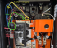
  • the two primary CTs are built into the Gateway
  • the solar CT was clipped onto the right cable by the installer and matches the Enphase data (after doubling it)
  • the main panel is upstream of the backup panel
  • Two additional CTs were clipped around the two steel lugs in the main panel and correspond to the secondary CT2 & CT3
 
So the gateway (backup panel and solar) is a sub panel off the main panel? If so the gateway load needs to be subtracted from main panel CT. I don’t know that setting.

What loads are backed up?

Gateway crisscrosses at some point internally, so watch for that. Measure voltage to check phase of CT’s, zero means same phase.
 
Last edited:
So the gateway (backup panel and solar) is a sub panel off the main panel? If so the gateway load needs to be subtracted from main panel CT. I don’t know that setting.
Do you have a sketch of how things are wired and where the CTs are installed? That might help us troubleshoot. If CT2/CT3 are on main panel after the meter, you might have to turn off the CTs in the Gateway. It all depends on how things are setup.
 
Thank you for all responses so far.
Do you have a sketch of how things are wired and where the CTs are installed?
That's a good question, I did not have a sketch, so I made one:
pws.png

Secondary CT2 CT3 are on the main panel, but before the meter. Without those the Powerwall wouldn't discharge for loads in the main panel like the EV.
I would check the configuration on CT2 and CT3 to make sure you're properly measuring both Phase A and Phase B.
I ordered a clamp meter to put right next to the CTs. That way I can compare what the gateway sees and what I see on a clamp meter. I hope that gives me some answers. I will report back once I get it.
 
I also wanted to add that the under reporting of the grid measurement happens both ways. On one day for instance when the battery was full already at shortly after 1pm, you can see the swap from the green line (charging the battery) to the white line (exporting to the grid).
Again, the white line should continue roughly on the same height as the green line, as the solar production kept up.
The error in the grid measurement results in a cascading error in the home load, which indicates a jump up in the data every time the battery hits 100% during a day while solar is still producing, even though there is no change in consumption.
Screenshot 2023-04-28 at 10.44.52 AM.png
 
Are CT2/CT3 setup as Site? They should be. You should also disable CT1/CT2 (in the Gateway) since those are going to mess up the calculations anytime the solar or Powerwalls are in the loop.

FYI, your backup panel is probably tied into the Gateway and not the main panel like you showed. The breaker in the main panel should feed the power into the Gateway.
 
Are CT2/CT3 setup as Site? They should be.
Yes they are.
You should also disable CT1/CT2 (in the Gateway) since those are going to mess up the calculations anytime the solar or Powerwalls are in the loop.
Ah that is interesting! That’s a setting I haven’t tried out at all yet. I will try that out. This actually sounds plausible. As described in my post above in my experiments I had the most accurate readings when I flipped CT2. Even though that is weird, because in the gateway the power flow is pretty clearly marked with arrows. None of the primary CTs should need flipping I thought. It makes sense that they actually need to be switched off. In my case they might have just mostly canceled each other out, but not quite.

If I switch off CT1/CT2, will it still measure the loads that are on the backup panel like the AC?

FYI, your backup panel is probably tied into the Gateway and not the main panel like you showed.
Ah yeah you’re right about that. I got that wrong in the drawing.
 
If I switch off CT1/CT2, will it still measure the loads that are on the backup panel like the AC?
Yes, it should work fine like that. The Solar CT measures solar generation. The Powerwalls have their own built-in monitoring that's reported to the Gateway. The Site CTs are just used to monitor any other energy going to/from the grid. The ones built into the Gateway are used when they are right behind the meter (whole house backup) or when you can't get CTs on the main power feeds so you have to put the secondary CTs on a branch off the main panel. Since you're able to put the secondary CTs right behind your meter, you don't need the primary CTs in the Gateway. Because your primary and secondary are directly inline with each other things are being double counted and throwing off the numbers.

There's not a good picture of your situation in the installer's manual unfortunately.

Powerwall 2 AC Installation Manual
  • Internal Primary Meter (Meter X) – This Site meter may be used when the Grid connection is at the Supply terminals. No additional steps are needed during install. If there are any loads or solar upstream of the Supply terminals, a Remote Meter must be used to meter the Grid connection point.
 
Last edited:
  • Helpful
Reactions: BGbreeder
Alright, so today I tried switching off the primary CTs (I set them to 'None' in the Tesla Pros app) and it got me closer, but still not all the way there yet. You're right, after reading the installation manual again, I also believe that it's right to only use the secondary CTs with my setup and switch off the primary. However the grid measurement is still underreporting, just like before.

Here is the data from an experiment after switching off the primary CTS, where I charged the car from the battery, then the grid, then the battery again (by changing the backup reserve slider) with 10A. You can see that the grid is still majorly underreporting. There was no major change in load during the time of the test, definitely no jump of 1.2kW right at the time when it switched.
Screenshot 2023-04-30 at 10.33.02 PM.png
The white line should be the same height as the green lines.

Tomorrow I will get my hands on a clamp meter. I hope with that I can verify the secondary CT readings.

Do you have any other idea why the grid could be underreporting so much?
 
Alright, so today I tried switching off the primary CTs (I set them to 'None' in the Tesla Pros app) and it got me closer, but still not all the way there yet. You're right, after reading the installation manual again, I also believe that it's right to only use the secondary CTs with my setup and switch off the primary. However the grid measurement is still underreporting, just like before.

Here is the data from an experiment after switching off the primary CTS, where I charged the car from the battery, then the grid, then the battery again (by changing the backup reserve slider) with 10A. You can see that the grid is still majorly underreporting. There was no major change in load during the time of the test, definitely no jump of 1.2kW right at the time when it switched.View attachment 933431The white line should be the same height as the green lines.

Tomorrow I will get my hands on a clamp meter. I hope with that I can verify the secondary CT readings.

Do you have any other idea why the grid could be underreporting so much?
Humm...
Could you show a log where you step the vehicle charge current by 5 or 10 amps while on grid power? That will give a solid indication of the grid CT accuracy.
Could do the same for PW mode also.
 
  • Like
Reactions: MP3Mike
Can you show us how the three CTs are configured in the app? If you get them on the wrong phases you'll get weird readings too.
That is a good point. After your suggestions it looks like this:
  • Primary CT1 & CT2 set to none
  • Secondary CT1 set to Solar and '1CT x2'
  • Secondary CT2 set to Site, not flipped
  • Secondary CT3 set to Site, flipped. The selected phase is L2
I was pretty surprised that CT3 had to be flipped, because both CTs are installed in the same direction in the main panel (see attached picture of the CTs in the main panel). I thought either both should be flipped or both shouldn't be flipped, but not either or. I tried unflipping them both, but that always resulted in totally wrong readings (like no load at all while the car is charging and solar is off. Or while the solar is on and the car wasn't charging it resulted in >10kW readings for no reason).

So I did try to select phase L1 for the Secondary CT3 and unflipped them both. So that changes the last two bullets to:
  • Secondary CT2 set to Site, not flipped
  • Secondary CT3 set to Site, not flipped. The selected phase is L1
This actually resulted in mainly correct readings, just like before.

But even with this new setting the remaining issue is that the grid consumption is lower than the battery consumption when I run my test with consistent load and switching back and forth via the backup reserve slider.

I did study the Tesla Powerwall installation manual a bit more and noticed a key difference to my setup:
The wiring diagram on page 54 corresponds most to my setup. But in my setup the installer put the Secondary CT2 & CT3 clamps around the steel lugs upstream of the main breaker, between the main breaker and the meter. In the installation manual they show to clamp the Secondary CT2 & CT3 only around the non - backup loads (see screenshot).
Could this have an influence on my false grid reading?
Screenshot 2023-05-01 at 12.32.54 PM.png


Picture of the CT clamps in my main panel, upstream of the main breaker:
They are not Tesla CTs, but some other brand because the Tesla CTs are only for 100A and were too small for the steel lugs.
Screenshot 2023-05-01 at 12.37.22 PM.png


Picture of CT wires in Tesla Gateway:
screenshot-2023-05-01-at-12-34-45-pm-png.933616


Could you show a log where you step the vehicle charge current by 5 or 10 amps while on grid power? That will give a solid indication of the grid CT accuracy.
Could do the same for PW mode also.
When I get my CT clamp (hopefully today) I will post an update comparison between what the Gateway sees and what I can see on the CT clamp. That should also verify that the CTs in the main panel read the right values.
 

Attachments

  • Screenshot 2023-05-01 at 12.34.45 PM.png
    Screenshot 2023-05-01 at 12.34.45 PM.png
    815.4 KB · Views: 341
I did study the Tesla Powerwall installation manual a bit more and noticed a key difference to my setup:
The wiring diagram on page 54 corresponds most to my setup. But in my setup the installer put the Secondary CT2 & CT3 clamps around the steel lugs upstream of the main breaker, between the main breaker and the meter. In the installation manual they show to clamp the Secondary CT2 & CT3 only around the non - backup loads (see screenshot).
Could this have an influence on my false grid reading?
Screenshot 2023-05-01 at 12.32.54 PM.png
That difference is beacuse in the drawing the grid total is the combined non-backup CTs + the gateway's built in CTs.

They are not Tesla CTs, but some other brand because the Tesla CTs are only for 100A and were too small for the steel lugs.
Ah! Are you sure they have the same output level per amp of current?
 
That difference is beacuse in the drawing the grid total is the combined non-backup CTs + the gateway's built in CTs.
I understand, so that means in that drawing one would set
Primary CT1 & CT2 as well as Secondary CT2 & CT3 to ‘Site’, while in my case I have to set
Primary CT1 & CT2 to ‘None’ and Secondary CT2 & CT3 to ‘Site’.
So it’s nothing that has to be physically changed in my setup.
Did I understand that correctly?

Ah! Are you sure they have the same output level per amp of current?
No I’m not sure. This is just what the installer put in after the Tesla CTs didn’t fit.
It is very likely that the issue lies somewhere here. The installer didn’t feel confident about this part and wasn’t sure if there is a solution at all after he tried to install the Tesla CTs and they didn’t fit. He then called a more senior tech in his company who said to install these other CTs, which my installer then did.

How can I go about finding out if those off-brand CTs have the right specs? If they have a different output level per amp of current, can I correct for it in software?
 
I understand, so that means in that drawing one would set
Primary CT1 & CT2 as well as Secondary CT2 & CT3 to ‘Site’, while in my case I have to set
Primary CT1 & CT2 to ‘None’ and Secondary CT2 & CT3 to ‘Site’.
So it’s nothing that has to be physically changed in my setup.
Did I understand that correctly?
That sounds correct, but I've zero real world experience, @Vines ?
No I’m not sure. This is just what the installer put in after the Tesla CTs didn’t fit.
It is very likely that the issue lies somewhere here. The installer didn’t feel confident about this part and wasn’t sure if there is a solution at all after he tried to install the Tesla CTs and they didn’t fit. He then called a more senior tech in his company who said to install these other CTs, which my installer then did.
That would explain things. Your graph from before shows grid is only 2/3 of the wall connector load.

How can I go about finding out if those off-brand CTs have the right specs? If they have a different output level per amp of current, can I correct for it in software?
Even without a clamp meter, you can have the car charge at two levels and compare the readings. Heck, not charging and charging works too. Car display should be close enough once it settles (or wall connector readout? ).

Maybe there is a scaling option somewhere?
 
Okay so I have a relevant update. The clamp meter got delivered and I compared all CTs as reported by the Tesla Pros app with the clamp meter values. As expected by now, the readings on the Secondary CT2 & CT3 are way off, while the Primary CT1 & CT2 are close enough within range.

The Primaries are off by at most 0.2A, while the Secondaries are off by 1.5 - 2A under the current load. I'm sure that's relative so under different loads the error would probably be larger.

Seen by Tesla GatewaySeen by clamp meterError
Primary CT19.328 A9.5 A0.172
Primary CT212.857 A13 A0.143
Secondary CT23.195 A5.2 A2.005
Secondary CT32.623 A4.1 A1.477

I also did some research on the CTs my installer installed. It's these ones:
Acrel AKH-0.66 K24 Split Core Current Sensors 200A/40mA
Aliexpress link

In the tesla installation manual they recommend the wireless Neurio Energy Meter (Tesla P/N 1112484-00-x) for 200 Amp CTs.
I'm not exactly sure what the difference is, but I did notice in this ebay post and this youtube post, that their ratio is 200A/66.6mA.

Is this the reason why my grid readings are off? Do I just have to ask the installer to install the correct CTs? Or could there be any other reason they are off?

All measurements:
Screenshot 2023-05-01 at 5.05.36 PM.png


Maybe there is a scaling option somewhere?
I looked for this but didn't find anything in the Tesla Pros app.
 
  • Like
Reactions: mongo and jgleigh
Is this the reason why my grid readings are off? Do I just have to ask the installer to install the correct CTs? Or could there be any other reason they are off?
Yes, wrong ratio CTs would be the source of your problems. Installer needs to use the correct 200A/66.6mA CTs.

5.2A x 40mA/66.6mA = 3.12A which is very close to the reading you got.
 
Primary CT1 & CT2 as well as Secondary CT2 & CT3 to ‘Site’, while in my case I have to set
The setup in the manual is for when the non-backed up loads branch off from the main panel, but you can't get the CTs on the main lugs (my setup is like this). Your setup is much simpler, you just need to get CTs that are scaled properly and I believe you'll be all set.
Primary CT1 & CT2 to ‘None’ and Secondary CT2 & CT3 to ‘Site’.
This is correct for how your system is wired.
 
Last edited:
Secondary CT3 set to Site, flipped. The selected phase is L2
This worked because you're referencing the wrong phase, but backwards. Works ok for 240V loads, but it would be off for 120V loads since they only exist on one phase or the other.
Secondary CT3 set to Site, not flipped. The selected phase is L1
This is correct and how it should have been from the start. CT2 is referenced to L2 and CT3 should be referenced to L1.