Bricks 47 and 48 are still not showing up at all. Cell 46 is down to .595v now after being at 2.837v on Thursday. When I tilted, the numbers changed a bit in both 46 and 45. When I scanned on the first day, brick 45 was at 3.922v like all of its friends but today it was resting at 3.913v before the tilt test and dropped to 3.781 with the left side up and then back to 3.917 with the right side up. The car is level now and #45 is at 3.873 after tilting back and forth. At 4pm, brick 46 was down to .643 so it dropped more during the tilt test. Brick 44 and 49 (either side of the current issue) are both at 3.923 which is where most of the pack is sitting.so sounds like water got in the module tray
this way its shorting 2 brick plates but that should drain 2 bricks...
i made a sketch of that scenario in this post:
something not adding up... is other 2 bricks still not showing up?


Welcome to Tesla Motors Club
Discuss Tesla's Model S, Model 3, Model X, Model Y, Cybertruck, Roadster and More.
Register
Install the app
How to install the app on iOS
You can install our site as a web app on your iOS device by utilizing the Add to Home Screen feature in Safari. Please see this thread for more details on this.
Note: This feature may not be available in some browsers.
-
Want to remove ads? Register an account and login to see fewer ads, and become a Supporting Member to remove almost all ads.
You are using an out of date browser. It may not display this or other websites correctly.
You should upgrade or use an alternative browser.
You should upgrade or use an alternative browser.
2014 P85d High Voltage Failure
- Thread starter mr_hyde
- Start date
so sounds like water got in the module tray
this way its shorting 2 brick plates but that should drain 2 bricks...
i made a sketch of that scenario in this post:
something not adding up... is other 2 bricks still not showing up?
Once the pack opens and up and if actually see < 1v on a brick. I'm assuming the brick is dead for good? Don't think ever want to discharge Lithium Ion to that low level right?
brainhouston
Active Member
Some people revive dead batteries but it's not recommended...Once the pack opens and up and if actually see < 1v on a brick. I'm assuming the brick is dead for good? Don't think ever want to discharge Lithium Ion to that low level right?
However brick could still be ok if it's just sense wires or bmb corroded and reading wrong voltages...
However brick could still be ok if it's just sense wires or bmb corroded and reading wrong voltages...
Yep, thats the hope... and seeing voltages go up based on tilt would suggest can't trust the readings
")
Herrstrand
New Member
Hi, looking at your voltage read out pictures, ignoring the two missing and the low 46 while assuming the total voltage is correct, it looks like you are missing around 12V to get to 377V. That is around 4 volts per missing block. Implying that the strange voltage readouts are wrong.
Hi, looking at your voltage read out pictures, ignoring the two missing and the low 46 while assuming the total voltage is correct, it looks like you are missing around 12V to get to 377V. That is around 4 volts per missing block. Implying that the strange voltage readouts are wrong.
Nice analysis! SMT shows 377v total (3.923 x 96) which means all bricks are ~3.923. Thus, error must be module 8's BMB's voltage sensor circuit due to liquid ingress (tilt test). Good news for OP
Its possible the remove the hump without the big battery lid ( link ) so probably relatively simple job : - remove reseal fuse cover, change fuse.
- Remove hump, module 8, fix voltage sensing circuit, clean dry out moisture, check overall condition, check the 2 BMB high failure caps.
- Check umbrella valves for moisture... replace with updated part.
- And maybe do contactors if feel adventurous haha.
Pack is a reman (Brown hump) Part sticker is no longer present.
Last edited:
Herrstrand
New Member
Sounds doable. I hope you are lucky with the circuitry clean up and fix. It is also interesting to know where the water if any entered your battery. I’m planning to do some preventive maintenance on my battery before the winter comes and are looking for weak points like the umbrella valves etc.
Sounds doable. I hope you are lucky with the circuitry clean up and fix. It is also interesting to know where the water if any entered your battery. I’m planning to do some preventive maintenance on my battery before the winter comes and are looking for weak points like the umbrella valves etc.
Yes if drop goes smooth, I may consider dropping my pack for preventive servicing and cleaning. Here are my battery's stats
- 13MS85 RWD, 9919 vin so first 10k vehicles. Original pack, 78k miles. Never problem. Never dropped and open for any reason.
- 21mV imbalance at 70% SOC (my normal charge limit but higher at 80+ and 60% SOC, as much as 40mV) in module 10 (2nd module behind passenger front tire)) Doesn't appear the pack can rebalance itself (multiple attempts, stepped SOC in 10% steps down and up with few hour wait in each step, then charge to 95% SOC for 1/2 day, saw 4mV improvement once but quickly returned to 21mV @ 70% SOC) Here are links to this effort link link
- plastic vented cover over umbrella valve have vent covered with wet dirt on both driver/passenger front 1/2 of the battery pack. Dug out as much as I could externally
- fuse cover looks okay
- Seattle rainy weather but no salted roads. Car garaged at home and work. Retired and car now is not driven on rainy days and hand washing car doesn't soak/rince down windshield run off post windshield runoff study ( link )
BTW, if you look at my complete SOC sweep of brick imbalance. I'd imagine BMS is watching the same history AND likely also temperature (2D matrix of data) to decide the health of the battery. I'm thinking replacing 1 module is entirely possible but have to match voltage across this entire 2D matrix. With a 85kWhr pack, its really time consuming to do this kind of sorting. And there are no suppliers with modules that has done this kind of sorting.
Some updates on this...
I dropped the pack last night and started to check things out. It was actually incredibly easy with just 2 ramps, 2 jack stands and 3 floor jacks. I had my neighbor help me work one of the jacks but I could have done it solo if I had to. Getting it back up aligned and level will take much more time and many more hands to get it right!
The pack is bone dry inside without even any sign of condensation. I got the hump off and now I'm a little stuck. The bus comes up from Module #7 and connects to #8 (which I'm trying to get out) and runs in tandem with the + bus that goes back to the contactor. The video from the Russian guys that are repairing Module #9 show that bus pulled up but it is with a newer revision pack that has the fuse cover on the bottom. With the fuse on the top, I don't see a good way to wrestle this out (safely) with nearly the full pack voltage potential.
The top photo is mine with the top-cover fuse and the bottom is a screenshot from the video with the bottom mount. I'm going to sleep on it and see if I'm missing anything easy. If not, I'm going to need to peel the first part of the pack to break that bus bar.
Other items - My fuse is the old style wire-in-sand-and-ceramic. I should update this, yes? The umbrella valves look great. There was a lot of dirt and gunk in the rail covers but annual maintenance with a shopvac and pick will keep them from getting packed so much that the umbrella starts sitting in mud. Not sure how big of a deal that is but it would be impossible for me to put it back together like that! LOL!!
BMB is 1050951-00-A REV01. Does that give a hint at what revision battery I have? It was a new pack from 2015, not refurbished as previously reported.
brainhouston
Active Member
i didn't see a pack with fuse on top but i'd think its the same setup just flipped fuse
if u remove the fuse box u should be able to swing it out
do u have this bolt:

if u remove the fuse box u should be able to swing it out
do u have this bolt:
Posting for OP as he is at my house with the pulled suspect module.
OP removed the bottom hump module by just bending the front of the big lid a little (remove a bracket securing bottom hump module). NOTE this is most dangerous as the 14 module in series is still connected and on one side of the fusebox (300+ volts).
The bottom hump module inspects fine (all sensor wires are 0 ohm from plate back to BMB board) So OP asked is this really module 8? (brick 46-48 are suspect failures so 46-48 / 96 x 16 are all 7.x or module 8)
Internet provides 2 different answers on location of module 8
- This famous pack architecture summary pic notes 8 is on bottom of the hump

 circuitdigest.com
- This TMC member fixed module 5 and a @red_five posted noted a different module # pattern (2nd link)
 teslamotorsclub.com
teslamotorsclub.com
teslamotorsclub.com
Anyone know which pattern is correct?
I guess an additional question using ScanMyTesla as a diag tool. Does its brick #s follow HV serial bus sequence or Tesla module # sequence? Having 2 different sequence makes referencing numbers a complete mess haha.
OP removed the bottom hump module by just bending the front of the big lid a little (remove a bracket securing bottom hump module). NOTE this is most dangerous as the 14 module in series is still connected and on one side of the fusebox (300+ volts).
The bottom hump module inspects fine (all sensor wires are 0 ohm from plate back to BMB board) So OP asked is this really module 8? (brick 46-48 are suspect failures so 46-48 / 96 x 16 are all 7.x or module 8)
Internet provides 2 different answers on location of module 8
- This famous pack architecture summary pic notes 8 is on bottom of the hump
Tesla Model S Battery System: An Engineer’s Perspective
So, in this article, we will be discussing the Battery system of the Tesla Model-S. We will majorly focus on the battery pack and briefly go through other topics such as Mechanical or thermal specifications. We will be digging deeper into the Electrical features and characteristics, the cell...
circuitdigest.com
- This TMC member fixed module 5 and a @red_five posted noted a different module # pattern (2nd link)
bad cell 2013 s
got the fatal display battery charge level restricted and car turns off module # 5 has a weak cell and for the extra bonus no warranty has anyone has any luck opening the pack swapping out 1 module with a good known besides grubber motors who snips and cut cell out its a long haul from new york...
teslamotorsclub.com
Anyone know which pattern is correct?
I guess an additional question using ScanMyTesla as a diag tool. Does its brick #s follow HV serial bus sequence or Tesla module # sequence? Having 2 different sequence makes referencing numbers a complete mess haha.
Last edited:
Posting for OP as he is at my house with the pulled suspect module.
OP removed the bottom hump module by just bending the front of the big lid a little (remove a bracket securing bottom hump module). NOTE this is most dangerous as the 14 module in series is still connected and on one side of the fusebox (300+ volts).
The bottom hump module inspects fine (all sensor wires are 0 ohm from plate back to BMB board) So OP asked is this really module 8? (brick 46-48 are suspect failures so 46-48 / 96 x 16 are all 7.x or module 8)
Internet provides 2 different answers on location of module 8
- This famous pack architecture summary pic notes 8 is on bottom of the hump
Tesla Model S Battery System: An Engineer’s Perspective
So, in this article, we will be discussing the Battery system of the Tesla Model-S. We will majorly focus on the battery pack and briefly go through other topics such as Mechanical or thermal specifications. We will be digging deeper into the Electrical features and characteristics, the cell...
- This TMC member fixed module 5 and a @red_five posted noted a different module # pattern (2nd link)
bad cell 2013 s
got the fatal display battery charge level restricted and car turns off module # 5 has a weak cell and for the extra bonus no warranty has anyone has any luck opening the pack swapping out 1 module with a good known besides grubber motors who snips and cut cell out its a long haul from new york...bad cell 2013 s
got the fatal display battery charge level restricted and car turns off module # 5 has a weak cell and for the extra bonus no warranty has anyone has any luck opening the pack swapping out 1 module with a good known besides grubber motors who snips and cut cell out its a long haul from new york...
Anyone know which pattern is correct?
I guess an additional question using ScanMyTesla as a diag tool. Does its brick #s follow HV serial bus sequence or Tesla module # sequence? Having 2 different sequence makes referencing numbers a complete mess haha.
Posting an update. Module Network Order differs from HV bus order. ScanMyTesla seems to be network order. Read link at bottom.
Also NOTE the maximal HV danger pulling the 2 front hump modules first as they are at the end of the 16 serial module chain. 14 remains connected after fuse pull and still packing nearly full pack voltage and current that can kill a person.
Log into Facebook
Log into Facebook to start sharing and connecting with your friends, family, and people you know.
 www.facebook.com
Last edited:
Hello everyone - a lot of progress today!
First, I need to echo Howard's comments about module 8&9 being the worst part of the pack to work with. I certainly don't recommend it. Working in the pack is never 'safe' but splitting modules in the middle to halve the voltages and then repeating a couple times where the lugs are relatively easy to reach is a much better approach. My pack has never thrown a low isolation fault so that would have caused me to take a different path completely. Howard has been basically pleading with me to NOT try any of this for a couple of weeks now - even came over to explain the dangers to my wife. He wasn't present for the pack removal or any of the tear-down. Please don't try this at home.
With that disclaimer out of the way, we found the culprit. The C27 and C26 caps are shot on the BMB for Module #8. While it was on the bench, we did check the voltage at each brick at the harness and they came back at a perfect 3.91v each with no variance. The cells are fine - great even. The pack itself is incredibly clean and there is no sign of moisture or even any condensation. The BMBs I have are 1050951-00-A REV01. It is exciting to find the acute issue so now I need a path forward. Some questions for the experts:
1. This BMB needs a repair but is it crazy to think another cap failure isn't right around the corner on one of the other 15? Module 9 has some discoloration starting where it contacts the plastic shield. Is refreshing these part of the basic recell or 057 service when they send a customer out with a refreshed pack?
2. Is my best path to repair this BMB or replace (one unit or 16 depending on the answer above)? If replace, is there a significantly better revision to this part I should consider? If replace, what hoops do I need to jump through to make the BMS happy about the new kid(s) on the block? If repair, who would provide this service?
3. Is there anything else on the BMB that should be refreshed or updated? Anything else in the pack for that matter?
Depending on what the group recommends, I am perfectly willing to tear the rest of the pack down and harvest the other 15 BMBs for repair or replacement. My labor/time is not the priority. My priority is making this pack solid from all known failure points for the foreseeable future. Eventually, a cell will fail and I'll cross that bridge when it happens. Thank you for all of the support!
brainhouston
Active Member
easiest is to replace those 2 caps n test the output from bmb but i don't know how to do it
there's info floating out there on how to hook up to read off bmb...
if it was me i'd probably just put the pack back in without sealing to verify operation (what i did with mine n iso issue)
how did u verify those 2 are shot? are they showing short on ohm meter?
there's info floating out there on how to hook up to read off bmb...
if it was me i'd probably just put the pack back in without sealing to verify operation (what i did with mine n iso issue)
how did u verify those 2 are shot? are they showing short on ohm meter?
how did u verify those 2 are shot? are they showing short on ohm meter?
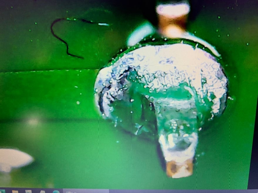
Didn't test the cap (can only test for short in circuit, probably should have done that) The pic actually don't do justice on how bad the caps look due to lighting. C27's top bulge is like bright green clump under magnifying eyewear haha.
Didn't test the fuses on the 7 voltage sensor wire lines on BMB. I wonder if 1 has burnt out given 2 missing bricks on SMT scan (0 or 5v don't display) But def onto board repair + bench test if possible next.
if it was me i'd probably just put the pack back in without sealing to verify operation (what i did with mine n iso issue)
SMT dev also told me can wire up a BT OBD2 dongle to a connector that connects to BMS (maybe right on rapidmate connector? looks close) along with 12v supply to scan the pack before install. @mr_hyde is interested to rig that up before sealing pack backup. Install without lid is def an alternative way to test without building more tools
Here is the full BMB. Chad mentioned on the facebook discussion that the part number doesn't necessarily show what is needed. It sounds like these caps can be replaced with some soldering skills but it was also suggested to just buy a new BMB from ebay. If I went that route, what programming/addressing would be needed?


C27 was so badly corroded that the pad was gone. I've ordered some new BMBs from ebay and will inspect the rest for corrosion and rubbing from the plastic covers especially around C26/C27. Anything that has been rubbed will get a new application of conformal coating.
Herrstrand
New Member
From the pictures it looks like the corrosion on the capacitors are partly shorting them and leading to wrong capacitance and function. If the C27 pads towards the board was still intact I suspect a good cleaning of them including under might do the trick, but if you have to reassemble and reinstall the pack just to check I would also opt for new BMB boards. Still would be interesting to see what those capacitors are doing in the circuit, sampling values, filter or something.
Sunday update: Removed all of the modules today to check things out. There are a total of 4 BMBs with significant corrosion that need to be replaced - all on 26/27. They are either touching the plastic cover or in such close tolerance that condensation is accumulating on both sides and bridging across. My pack was bone dry with no signs of water ingress. There was no water in the pack, but there was certainly moisture. I'm extremely glad I didn't just fix the immediate problem and close things back up or one of these would have failed again in weeks or months. Do you think Tesla inspects the BMBs for corrosion when they fix-n-flip to 'refurbish' a pack?
The moisture was all near the front of the pack. We suspect it is coming through the vent but this is Seattle which is rainy, but basically has no humidity compared to many other places in the country. Mercedes EVs have desiccant cartridges in the batteries which would be a great upgrade for us if there was any room.
The moisture was all near the front of the pack. We suspect it is coming through the vent but this is Seattle which is rainy, but basically has no humidity compared to many other places in the country. Mercedes EVs have desiccant cartridges in the batteries which would be a great upgrade for us if there was any room.
Similar threads
- Replies
- 5
- Views
- 206
- Replies
- 17
- Views
- 1K
- Replies
- 22
- Views
- 5K
- Replies
- 16
- Views
- 2K
- Replies
- 14
- Views
- 891