Seems like it would be an easier way to go in many cases, potentially eliminating the need for panel upgrades, 120% rule, etc. I've seen it mentioned a few times in this forum but I can't find a clear answer to this yes or no question.


Welcome to Tesla Motors Club
Discuss Tesla's Model S, Model 3, Model X, Model Y, Cybertruck, Roadster and More.
Register
Install the app
How to install the app on iOS
You can install our site as a web app on your iOS device by utilizing the Add to Home Screen feature in Safari. Please see this thread for more details on this.
Note: This feature may not be available in some browsers.
-
Want to remove ads? Register an account and login to see fewer ads, and become a Supporting Member to remove almost all ads.
You are using an out of date browser. It may not display this or other websites correctly.
You should upgrade or use an alternative browser.
You should upgrade or use an alternative browser.
Does Tesla ever install solar + powerwall systems using Line Side Tap? (In California with PG&E)
- Thread starter Yonki
- Start date
Tesla has a new Backup Switch that is a meter adapter ring mounted between the meter and its socket. It's not a line-side tap; instead, it is a grid isolation device (a relay) that is controlled by a low-voltage cable to the Powerwall+. That allows whole-house backup to be implemented just by connecting the Powerwall+ to the main service panel via circuit breakers. But as far as we know it has not been approved yet by PG&E.

FurryOne
Member
I'm hoping that National Grid (NY) approves the B-U Switch quickly, since I've been here with one sitting in a box waiting for over a month now...As pointed out above the backup switch is the slick solution, and hopefully, it will be accepted soon.
Vines
Active Member
Last time PGE approved something like this it took about 18 months.I'm hoping that National Grid (NY) approves the B-U Switch quickly, since I've been here with one sitting in a box waiting for over a month now...
Good luck to you.
wwhitney
Active Member
The Backup Gateway is set up to hold a main breaker, which can be the service disconnectTesla does not allow PV plus Powerwall on a line side tap.
So if you have a a separate meter enclosure and can intercept the service conductors between the meter and the existing service disconnect, then that would be akin to a line side tap. I assume Tesla would support that, since the hardware is designed to support it.
But the main issue is that in California it is very common to have a meter main, so you can't do a line side tap or intercept the service conductors between the meter and the existing service disconnect.
Cheers, Wayne
cali8484
Member
Tesla has a new Backup Switch that is a meter adapter ring mounted between the meter and its socket. It's not a line-side tap; instead, it is a grid isolation device (a relay) that is controlled by a low-voltage cable to the Powerwall+. That allows whole-house backup to be implemented just by connecting the Powerwall+ to the main service panel via circuit breakers. But as far as we know it has not been approved yet by PG&E.
That sounds like the GenerLink which has been around for years in Canada but US PoCo's won't allow it. If PG&E approves Tesla's Backup Switch then GenerLink may finally get approved as well.
That’s exactly what I want - was that schematic from a real Tesla system? What state/country?Yes they support line side tap, maybe region/utility specific. Will need the back up gateway 2 and not the meter back up switch socket
wwhitney
Active Member
Again, what does your meter look like? If it's in a box with breakers as is common in California, doing what the diagram shows is much more expensive than other options. You'd need to get your service disconnected, that meter main box removed, and a new meter-only enclosure installed. Plus a subpanel if your meter main has distribution breakers. And if the meter main is recessed, your siding repaired.That’s exactly what I want - was that schematic from a real Tesla system? What state/country?
Cheers, Wayne
Here's what I've got now:Again, what does your meter look like? If it's in a box with breakers as is common in California, doing what the diagram shows is much more expensive than other options. You'd need to get your service disconnected, that meter main box removed, and a new meter-only enclosure installed. Plus a subpanel if your meter main has distribution breakers. And if the meter main is recessed, your siding repaired.
The house was rebuilt from the foundation up 2 years ago (I bought it a year ago). They generally did a fantastic job, though I can't think of a crappier 200A panel choice. They also violated two of the panel's specs - the panel supports a maximum of one 100A breaker, which has to be put in the lowest position. As you can see they installed a 120A breaker 2 positions above the lowest position. So I will need a new panel to pass inspection.
Anyway, it's a nice, new house, so I want to keep the wiring as clean and minimal as possible. Cost is not my #1 priority. I'm trying to avoid what Tesla did at my previous house (keeping the original main service panel & meter, adding a big junction box, adding an additional load center box, and running conduit everywhere).
Ideally I'd like to keep the loads where they are (so no need to splice all my wires in a new junction box and add an additional load box and deal with all the stucco and possible interior wall work that would entail). In an ideal world, where the existing panel was adequate, ther 120% rule didn't exist, and I could split my panel in half to separate the meter from the loads, the wall would look like this:
(The boxes and conduit for the Powerwalls, solar, and gateway on the wall around the corner can be laid out cleanly - I'm not worried about that part.)
So what I'm trying to figure out is how to come closest to this dream. As far as I can tell, you can't buy panels that have the meter isolated from the breaker bus (though that would be amazingly easy to do and it seems like it would be a great solution for a lot of solar installations).
Also, this is a 12kW/3 Powerwall install that Tesla signed off on (pending me upgrading the panel) 6 months ago. My goal is to get this work done by a local electrician before Tesla is ready to do their install.
Knowing that elegance is more important than cost, does anyone have any recommendations?
Cheers!
Vines
Active Member
EDITS below
The definition of line side tap as I use it is putting 2 different services on a single service.
So for instance if you have a combo panel, you put an insulation piercing connector like the KUP-L-Tap for the appropriate size wire and insulation you are using. https://rexel-cdn.com/Products/72C0...AC88/72C00A7C-B3E2-424F-874B-8BCA0849AC88.pdf This goes between the meter portion of the panel and the main breaker, on the customer side of the combo panel.
This would allow a PV installer to add a second "Service" for additional PV usually with a 60A or larger fused AC disconnect as close to the existing combo service panel as possible.
When there is a separate meter socket only, and then a subpanel as the service panel, the installation is super easy. As pointed out above, the Gateway is rated as service equipment, therefore once a main breaker is installed, it can be the new service entrance panel. Just disconnect the wire from the meter socket, to the subpanel, and put the Gateway 2 there, then connect the Gateway to both the existing 'Essential Loads' subpanel, and the 'Generation Panel'
Unfortunately, west coast services are 99% meter/main combo panels also known as CSED (Combination Service Entrance Device)
The only other legal way is to start talking crazy and call an NRTL for a field evaluation and re-list the CSED to a new configuration. In the very rare cases when we do this it's a lot of time and money to do it right. I haven't tried the configuration you are expecting, but there are a few potential issues. It's just not a smart path to go down.
Really if you want this done with no rework or other impact it's with the backup switch.
If you cannot get that approved or don't want to wait then I'd recommend relocating the loads to the interior or exterior wall and installing a new Main Breaker only panel and relocating the loads. The only way you see no conduit is if the new 'Essential loads panel' is right behind the existing main panel, or if you build a doghouse to hide it all. If you are willing to frame out and finish a bit of false wall on the interior it would be nearly invisible, except for the 6" bump out in the interior space.
The definition of line side tap as I use it is putting 2 different services on a single service.
So for instance if you have a combo panel, you put an insulation piercing connector like the KUP-L-Tap for the appropriate size wire and insulation you are using. https://rexel-cdn.com/Products/72C0...AC88/72C00A7C-B3E2-424F-874B-8BCA0849AC88.pdf This goes between the meter portion of the panel and the main breaker, on the customer side of the combo panel.
This would allow a PV installer to add a second "Service" for additional PV usually with a 60A or larger fused AC disconnect as close to the existing combo service panel as possible.
When there is a separate meter socket only, and then a subpanel as the service panel, the installation is super easy. As pointed out above, the Gateway is rated as service equipment, therefore once a main breaker is installed, it can be the new service entrance panel. Just disconnect the wire from the meter socket, to the subpanel, and put the Gateway 2 there, then connect the Gateway to both the existing 'Essential Loads' subpanel, and the 'Generation Panel'
Unfortunately, west coast services are 99% meter/main combo panels also known as CSED (Combination Service Entrance Device)
The only easy way you get exactly that is with the Backup switch. I could see you passing inspection easily with the existing panel, with existing violations. Often if it was overlooked once, it will be overlooked again, especially in PGHere's what I've got now:
View attachment 690274
The house was rebuilt from the foundation up 2 years ago (I bought it a year ago). They generally did a fantastic job, though I can't think of a crappier 200A panel choice. They also violated two of the panel's specs - the panel supports a maximum of one 100A breaker, which has to be put in the lowest position. As you can see they installed a 120A breaker 2 positions above the lowest position. So I will need a new panel to pass inspection.
Anyway, it's a nice, new house, so I want to keep the wiring as clean and minimal as possible. Cost is not my #1 priority. I'm trying to avoid what Tesla did at my previous house (keeping the original main service panel & meter, adding a big junction box, adding an additional load center box, and running conduit everywhere).
Ideally I'd like to keep the loads where they are (so no need to splice all my wires in a new junction box and add an additional load box and deal with all the stucco and possible interior wall work that would entail).
The only other legal way is to start talking crazy and call an NRTL for a field evaluation and re-list the CSED to a new configuration. In the very rare cases when we do this it's a lot of time and money to do it right. I haven't tried the configuration you are expecting, but there are a few potential issues. It's just not a smart path to go down.
(The boxes and conduit for the Powerwalls, solar, and gateway on the wall around the corner can be laid out cleanly - I'm not worried about that part.)
So what I'm trying to figure out is how to come closest to this dream. As far as I can tell, you can't buy panels that have the meter isolated from the breaker bus (though that would be amazingly easy to do and it seems like it would be a great solution for a lot of solar installations).
Also, this is a 12kW/3 Powerwall install that Tesla signed off on (pending me upgrading the panel) 6 months ago. My goal is to get this work done by a local electrician before Tesla is ready to do their install.
Knowing that elegance is more important than cost, does anyone have any recommendations?
Cheers!
Really if you want this done with no rework or other impact it's with the backup switch.
If you cannot get that approved or don't want to wait then I'd recommend relocating the loads to the interior or exterior wall and installing a new Main Breaker only panel and relocating the loads. The only way you see no conduit is if the new 'Essential loads panel' is right behind the existing main panel, or if you build a doghouse to hide it all. If you are willing to frame out and finish a bit of false wall on the interior it would be nearly invisible, except for the 6" bump out in the interior space.
OMG, I finally caught up enough to see what this new Tesla "Backup Switch" is all about. Yes, that's exactly what I want.  it gets (PG&E?) (CA?) approved soon. Thanks for the detailed info!
it gets (PG&E?) (CA?) approved soon. Thanks for the detailed info!wwhitney
Active Member
You'll still need to replace your current service panel, unless you are OK with having only 100A of load backed up behind the Gateway, with the rest of the loads not more than 70A individually, and your building department allows the early recognition of Powerwall as a Power Control System that can be configured to limit exports to 80A continuously (since you will have more than 100A * 80% of inverters behind your Gateway).OMG, I finally caught up enough to see what this new Tesla "Backup Switch" is all about. Yes, that's exactly what I want.
So if you are replacing the panel and don't want to wait on approval for the Backup Switch, the easiest and most elegant solution would be to find a flush mount 200A meter/main breaker and a flush mount 200A main breaker distribution panel that you could mount either side by side or with the meter/main over the distribution panel. That way you'd have a feeder from the meter/main to the distribution panel that you can intercept for interposing the Backup Gateway (which can be around the corner). I'm not very familiar with what sort of flush mount residential 200A products are available, but hopefully that would be possible.
Another possibility would be a new meter/main/distribution that has wire type conductors from the meter to the main breaker that the manufacturer says can be field modified. Not sure if such a thing exists. And then you'd need to mount your Backup Gateway right next to your meter, as it would have a main breaker that is your new service disconnect. A definitely available alternative along these lines is a separate meter enclosure and main breaker panel plus the Backup Gateway, and perhaps having them all surface mounted would look better than a mixture of flush and surface mounted (since the Gateway can't be flush mounted to my knowledge).
Cheers, Wayne
Yes it's the Tesla engineering drawing "01" "3 lines diagram" IL will county but it's not the city here than the county that permitThat’s exactly what I want - was that schematic from a real Tesla system? What state/country?
Vines
Active Member
All the new CSED I have seen have factory-installed and listed conductors certainly from the meter to the main breaker, and usually from the main breaker to the distribution bus lugs.Another possibility would be a new meter/main/distribution that has wire type conductors from the meter to the main breaker that the manufacturer says can be field modified. Not sure if such a thing exists. And then you'd need to mount your Backup Gateway right next to your meter, as it would have a main breaker that is your new service disconnect. A definitely available alternative along these lines is a separate meter enclosure and main breaker panel plus the Backup Gateway, and perhaps having them all surface mounted would look better than a mixture of flush and surface mounted (since the Gateway can't be flush mounted to my knowledge).
Cheers, Wayne
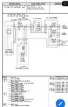
Many inspectors would allow what is shown below, as long as the wires from the main breaker to the distribution bus were field installed as they were in these older Milbank panels.
However the wire management in this case looks to leave something to be desired. There appears to be damage to one of the 100A conductors, as it crosses the sharp edge of the distribution bus.
This is a case where the customer had a previously installed generator, which backs up the main distribution bus, similar to what the OP wants. In this case I would be comfortable backing up the main distribution bus with a GW2 system, as long as the generator was properly connected.
wwhitney
Active Member
[CSED = Combination Service Entrance Device, a term for meter/main/distribution in one enclosure.]All the new CSED I have seen have factory-installed and listed conductors certainly from the meter to the main breaker, and usually from the main breaker to the distribution bus lugs.
One difficulty that I imagine that could be encountered when trying to replace factory installed conductors in a CSED with field wiring is that the manufacturer may have used smaller wires or tighter bends in the wire than the NEC would allow. So you might be left with inadequate bending space or needing to replace lugs to accommodate a larger wire. [Zero first hand experience on these possible issues.]
Also, if you intercept conductors from the main breaker/service disconnect to the gpanelboard main lugs, and route them to the Backup Gateway to provide whole house backup, you'll need to add another main breaker to protect the panelboard bus, which probably means another enclosure. If you are able to intercept the service conductors from the meter to the main breaker/service disconnect, then you can use the space for a line side breaker in the Backup Gateway to install a new service disconnect breaker there, and use the CSED main breaker to protect the panelboard bus.
But certainly I agree that the ability to do some of the above would be a nice option to have when dealing with adding the Backup Gateway to a premises with a CSED.
Cheers, Wayne
I get meter, but what's the distinction between main and distribution? I could see bus and breakers, but you really couldn't have one without the other, right?[CSED = Combination Service Entrance Device, a term for meter/main/distribution in one enclosure.]
The biggest battle may be learning all the terminology - appreciate you spelling out the acronyms, Wayne!
wwhitney
Active Member
The service conductors from the utility are always energized and minimally protected from short circuits, with no overload protection. So your service disconnect is a circuit breaker on the outside of the building, or inside right where the conductors enter the building. The service disconnect provides overload protection for the service conductors and short circuit protection for the system downstream of it. The meter will be located somewhere in/on the service conductors upstream of the service disconnect. And downstream of the service disconnect you will have a panelboard with multiple breakers for the various circuits (and possibly feeders) for the premises; that's what I'm calling distribution (maybe load center is a more common term).
All 3 function can be in separate enclosures: meter, service disconnect, and distribution. Or you could combine the service disconnect with the meter, or with the distribution, or both, like you currently have.
The Backup Gateway's disconnect functionality needs to be upstream of any distribution breakers you want backed up, but either downstream of the service disconnect, or containing a line side breaker which becomes your service disconnect. So for whole house backup it could be installed between the meter and (original) service disconnect, or between the service disconnect and the distribution. Or with a Backup Switch, that disconnect functionality gets installed physically at the meter, and logically between the meter and the service disconnect.
Cheers, Wayne
Last edited:
Vines
Active Member
Wire bending room is the number one thing that makes all of this difficult. The only successful field evaluations I have done are turning a CSED into a Meter socket enclosure, and UL certifying a line side tap to factory conductors inside a CSED. The rest is just theoretical, and not the KISS way to deal with this. The good options are outlined above.[CSED = Combination Service Entrance Device, a term for meter/main/distribution in one enclosure.]
One difficulty that I imagine that could be encountered when trying to replace factory installed conductors in a CSED with field wiring is that the manufacturer may have used smaller wires or tighter bends in the wire than the NEC would allow. So you might be left with inadequate bending space or needing to replace lugs to accommodate a larger wire. [Zero first hand experience on these possible issues.]
Also, if you intercept conductors from the main breaker/service disconnect to the gpanelboard main lugs, and route them to the Backup Gateway to provide whole house backup, you'll need to add another main breaker to protect the panelboard bus, which probably means another enclosure. If you are able to intercept the service conductors from the meter to the main breaker/service disconnect, then you can use the space for a line side breaker in the Backup Gateway to install a new service disconnect breaker there, and use the CSED main breaker to protect the panelboard bus.
But certainly I agree that the ability to do some of the above would be a nice option to have when dealing with adding the Backup Gateway to a premises with a CSED.
Cheers, Wayne
Similar threads
- Replies
- 64
- Views
- 6K
- Replies
- 30
- Views
- 3K
- Replies
- 10
- Views
- 2K
- Replies
- 7
- Views
- 2K
- Replies
- 61
- Views
- 10K