Welcome to Tesla Motors Club
Discuss Tesla's Model S, Model 3, Model X, Model Y, Cybertruck, Roadster and More.
Register

Roadster PEM failure

This site may earn commission on affiliate links.
The PEM is basically standard inverter electronics, so called h-bridge design.

H-bridge - Wikipedia

The non "digital" parts are standard electronics parts and IGBTs don't have to be "matched" like you would have to do in a hifi amp. The tricky part is the main board which you see immediately after opening the PEM and the software running it (boards in the front of the Roadster). Pete(r) Gruber in Phoenix and his team have done a lot of reverse engineering and also Carl Meadlok in Seattle. I don't know how far GS Technology has gone into the PEM 'til now.
If it's only blown IGBTs somebody with soldering knowledge should be able to do the exchange. Capacitors should be checked too since they age over time and there's at least one incident I am aware of where a bad cap blew up in a PEM - that didn't look nice :/
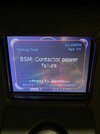
I had one row of IGBTs blown on one megapole and still the BSM fuses didn't blow... also wired battery minus and ground wrong way to the PEM... errors and little sparks... still no blown fuse... Guess I was damned lucky that time... carried the Roadster to SEC FRA to find out the wrong wiring... D'oh...
One more: don't use ceramic isolation stripes like I did... they are used in windmill inverters eg. but I had one broken due to vibrations and the type how they are mounted and the result was the blown IGBTs... The original gum like paste deteriorates over time which is the main cause for PEM breakdowns. I am not sure how Tesla handles this issue meanwhile in refurbed PEMs but a few years ago still this paste was used. A better solution is ceramic foil which I have now since 2.5 years installed by GS. Works.... :)
One more thing about PEMs and sport version. As I remember one PCB in the front was exchanged when Roadsters were upgraded to the sport version, imo it's mostly software based driving the megapoles harder than in the normal (software) version. But I might be wrong there.
 
  • Like
Reactions: driver_EV
Thanks for the info. I suppose each megapole is a half bridge with 14 IGBTs in parallel in each branch.

Status now is that I have shut down the car and also checked the fuses. Both gargantuan fuses on the inlet of the PEM are fine.
Tesla wants the car for diagnosis. I intend to indulge them. Then I will decide based on what they offer. Meanwhile I prepare for the most likely outcome which seems to be that I will try to fix it myself. Practically it doesn't sound to difficult, but I realize that there several things that can go wrong. It emboldens me that so much experience and insights into the matter are shared on this forum. That is one of the aspects that after all makes this car an interesting car to own.
 
The PEM is basically standard inverter electronics, so called h-bridge design.

H-bridge - Wikipedia

The non "digital" parts are standard electronics parts and IGBTs don't have to be "matched" like you would have to do in a hifi amp. The tricky part is the main board which you see immediately after opening the PEM and the software running it (boards in the front of the Roadster)

I am now in the position to add some more detail:
The three megapole boards are, as far as I can see, identical and each drives one phase, i.e. each board is like half an H-bridge (my apologies if am applying the wrong terminology, but the full three-phase setup doesn't look like an H). The 28 IGBTs are configured in four groups of 7 transistors each: Q1-Q7, Q8-Q14, Q15-Q21 and Q22-Q24. Each group is a row of transistors on the PCB. Two groups constitute the high-side (Q1-Q7 and Q15-Q21) with all their collectors connected to B+ and all their emitters to the output. The other two groups constitute the low-side with all their collectors to the output and alle their emitters to B-. There is a common drive signal for all transistors in a group. Each transistor is connected to the drive signal through a gate resistance of 7.5 Ohm which is implemented as two 15-Ohm-resistors in parallel. Each drive signal is shunted to the emitters by a 100 kOhm resistor. The seven electrolytes are all connected in parallel between B+ and B- and there is also something that looks like a film capacitor between the B+ and B- busbars. I have no information on the "choke" on the output. The drive signals enter the megapole board from the driver board through four pin-headers. I have not much to say about the driver boards, but I noticed that they employ the Microchip TC4451 MOSFET-driver.
 
similar that was quit hard to get off. There are also nylon spacers that need to be removed. All screws were cleaned and run up and down with the nuts until they were free. This was also quite time consuming. You have a total of 42 to clean up. I considered buying new ones but the size and the thread seemed unlike anything I could find in the local hardware shops...
From what I have been able to figure out, the bolts are M3.5-0.6 with dimensions as indicated in in this sketch:
megapole_fasteners_dimensions.jpg


I don't know what the material is. I checked it against A2, but it looks different. Probably it is some plated steel.
 
Hi Guys,
I am the owner of a 1.5 Roadster in Europe and got a Problem at charging:
923 DMC FW: LINE CURRENT NOTEQUAL REQUEST FAULT
925DMC HW Common MODE SENSE FAULT
1081DMC FW: Line OverFrequency warning
A Tesla techician means - it could be such a isolation Problem - do you have any experince with this faults?

Clemens
 
1.5ers have a different setup for charging (part of the motor coil is used) and the PEM is different partly in design and supposed to had "military grade" capacitors eg.... (better than the later 2.x)
From the messages I'm not really sure if it is an insulation (not isolation, we German speaking natives make this wrong translation a lot ;) ) fault.
Are you maybe nearby GS Technologies @ Berg (CH) ? Those guys could be a start to talk to.
Otherwise if you want to do it yourself to have a first look open up your PEM (PULL SERVICE PLUG or at least set car in INHIBIT APS MODE and CHECK FOR VOLTAGE in the little compartment box) and see if there's deteriorated insulation (little gaps in the gum, hard to see...) or any other visible damage like burn marks by a blown IGBT.
Btw. it does not charge, did it sill drive? Sometimes the DC/DC converter in the front goes south...
You might pull the service plug anyway to keep the battery from draining. Esp. with the 1.5ers it's urgent since they pull the 12v from two sheets of the battery!
What was your SOC when the error occurred?

Keeping the fingers crossed for you Clemens... have been there and it was a pain in the ass...

Daniel
 
  • Helpful
Reactions: drewski
Hi Everyone, I am helping a friend with his roadster. To make along story short, he had PEM issues with various fault codes. Many of the fault codes were cleared after the dielectric material was replaced. Now we are down to the last fault code "271 BSM Contactor Power Failure". After reading various threads in this forum, I have learned that the cause could be the inertia switch, moisture or a service plug problem. The handle to the orange service plug is broken, but could that really be the problem? The latch itself doesn't seem to do much. We've made sure that the plug is inserted all the way. We had a TESLA Ranger Technician diagnose the PEM and to ensure that the firmware was up to date and synced. Still the 271 fault code persists. We would be grateful for this groups help and assistance. I will be ordering a new service plug today.
 

Attachments

  • IMG_6303.jpeg
    IMG_6303.jpeg
    538.4 KB · Views: 90
Thanks everyone for your kind assistance. This makes perfect sense. I've ordered a new one from TESLA. In the meantime, I am going to pull the disconnect plug from my car and test it on my friend's car. Fingers crossed that this will clear the 271 fault code. The current plan is to perform the test on either Sunday or Monday. I will report back with a progress update. Thanks again.
 
  • Like
Reactions: eHorses
Thanks everyone for contributing to this thread!
The information in this thread gave me enough confidence to replace the insulation material.
With help from Peter who has a lot of electrical and PCB experience.

A couple of weeks ago I started getting the 905 error code: 905 DMC HW: PhaseA Low Side Desat Fault.
I ordered the insulation material mentioned in this thread: Softtherm 86/600 200x120x0.5mm.
And yesterday I replaced it.

The insulation material looked like this after 12 years and 144.000 km:

1672999683100.png


Removing the old insulation material:

1672999880149.png


Help from Peter who has a lot of electrical experience:

1673000121590.png


The new insulation material:

1673000152837.png


Yesterday evening I put the PEM back in the car and did a test drive.
Everything worked fine.
I hope this solved the 905 error code issue.

Gr,
Marcel
 
Hello everyone, good job guy.
I have a question, which material is better, or it can be a silicone gasket, or it can be mica for IGBT ?

your thoughts on this.

32840881.jpeg
 

Attachments

  • Знімок екрана 2023-02-17 о 20.40.29.png
    Знімок екрана 2023-02-17 о 20.40.29.png
    359.9 KB · Views: 56
That orange service disconnect is bane of newbies, break easy if you dont know how to pull it properly. I have a spare and I know Carl has a bunch them in stock.
Like Marco says "There's a microswitch in the batterycase", you can hear the micoswitch click when you flip down the handle if you listen carefully.
Tried to pull the service plug, but it seems to be stuck and the small handle seems fragile. Any particular trick involved in pulling it out ?