Welcome to Tesla Motors Club
Discuss Tesla's Model S, Model 3, Model X, Model Y, Cybertruck, Roadster and More.
Register

Safely trickle charge a bricked pack in/out of car - solution

This site may earn commission on affiliate links.
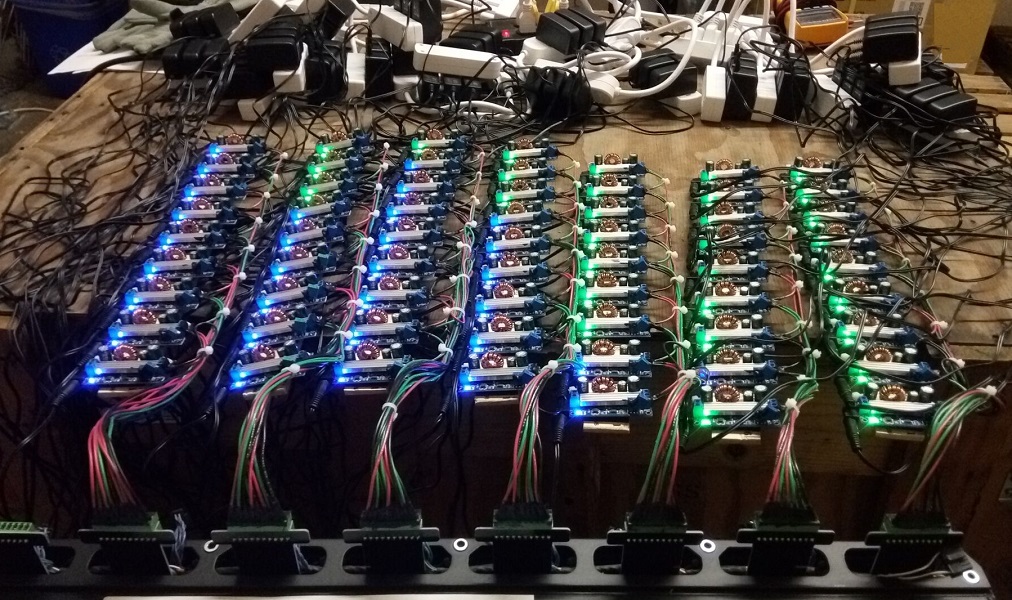
DollarTree have 3-way power strips for $1.

3 of those = 9 sockets, then one more 3-way power strip to power them = 4 power strips per sheet.
4 sheets plugged into a 4-way power strip and 3 sheets into another.

I ordered 100 power-supply/charging boards from China for $280 incl shipping. Then replaced the 50k Ohm voltage set trim pot with a 5.1k resistor and a 25-turn 1k trim pot to get the voltage-set accuracy needed. The current-set is a bit touchy as well but not as important.

Found a bad one this morning (high noise) - will replace it.
 
  • Informative
Reactions: dhrivnak
The first 7 sheets wired up...

ess_balancing_charge.jpg


This will get the bricks to a consistent voltage to correct for the oddities of storage discharge.

Then it will be up to the car to figure out the actual balancing needed by tracking what the bricks do over charge-discharge cycles.

(Theory - the lowest capacity brick should be the first to reach min-voltage when discharged and the first to reach max-voltage when charged. Pretty sure the balancing the car does is to make sure there are no charge-percent offsets big enough that another brick could reach Vmax/ or Vmin before the weakest brick does)
 
There are some nice lithium chargers with variable voltage and amps
https://www.ebay.ca/itm/DC-DC-Step-...e=STRK:MEBIDX:IT&_trksid=p2057872.m2749.l2649
I use these to balance parallel groups before connecting the BMS. They have gone up in price as they were 2.99 last year. I wonder if you can do the same with a hobby charger as they charge mutiple groups. it would make it far less cluttered. i was going to make the exact same thing jsut in case. I have a lot of just in case tools in my garage!
 
Seeing a quick where the BMB path to the most -ve brick in each sheet seems to have higher resistance.

What we really need is a constant current charge with a periodic stop-and-measure to check the voltage level.
 
Hello Nick. I was directed to this thread and your solution via XIr8 (thanks XIr8!). I posted my issue/request in another thread ("looking for local expert..."), some of it repeated below. I wanted to see if I can rent/lease/buy/borrow your "chargers," or better yet, if you are local, maybe even ask you to help me test and trickle charge the batteries (of course with compensation). If interested, please reply and we can connect directly to figure the details (I messaged you also). Here is part of my earlier post:
"Hello fellow roadster owners., I am an early adopter (2008-1.5) but had never signed up on the forum until my car (battery) died. Similar story to some of the other posts I read (was connected to 120V in storage mode and away from it for a few month not knowing the car has issues with this mode...). After taking it to Tesla and some more searches (including connecting 12V power source, etc.), my "main" options seem to be (1) upgrade to 3.0 (very expensive); (2) try to "revive" what can be salvaged and replace un-salvageable sheets (but no idea as to its cost but in case of full replacement its cost is close to full upgrade - and much higher if $/kWh capacity is considered); or (3) sell the car and say goodbye to Tesla once and for all! After a lot of effort (thanks to many posts and some guidance from PG in AZ) I finally downloaded a log file for the first time since I had the car. So...* Is there a local (in Bay Area, and more specifically East-Bay) "expert" whom I can connect with (hire) to help me figure out what is damaged/needs replacement so I can decide on my options? (for this, I understand we'd need to trickle charge the battery and see which responds??)
Thank you. .m (Manuchehr)
 
If anyone is looking for these boards I’m about to order some thanks to the generosity of nick putting the design on open source so we can easily remake them. Let me know if you want one-a couple or a whole set. Also @nick do you have part numbers for the connectors at each end so I can get them ordered up to. Once again Thankyou for the files.
 
If anyone is interested I finally got a few days off to go down to Miami and pick Nick’s boards up. There’s a few already spoken for but I’ll have some extras for anyone interested.
 

Attachments

  • 57237F79-E16D-49CB-9BE0-03D08FA7B12E.jpeg
    57237F79-E16D-49CB-9BE0-03D08FA7B12E.jpeg
    323.2 KB · Views: 137
OVMS has a new unified framework for display pack module voltages and temperatures. We've got a nice web-based chart, as well as machine-readable metrics. We've implemented it for Model S, and now looking at Roadster (using the OVMS 3 bus CAN diag cable for early Teslas).

I've identified and decoded about 90% of the information in the BMS CAN bus messages for sheet level voltages and temperatures. These are broadcast messages, seemingly from each BMS board - so 11 messages each for temperature and voltage. Kind of strange in that a multiplexor byte is not used to identify the sheet, but instead each message is transmitted with a unique ID (and no, they are not sequential - which slowed me down).

The voltage messages seem to have minimum, maximum, and average voltages (as well as two more bytes on the end that look like brick numbers, but not 100% certain of that). I am assuming that those are for all the bricks within that one sheet, as these values are per sheet (not per-brick). There must be something per-brick (as the VMS can display those in logs), but it doesn't seem to be broadcast (which will make things harder to find). But for charging/monitoring basis, per sheet is probably acceptable?

The temperature messages seem to have three individual readings for each sheet, plus one other byte that seems to be a multiplexor of some type. Maybe a brick level multiplexor - that is the 10% remaining I am working on?

Planning to put these in OVMS, for the display of battery status. But wonder if it is of any use for what you guys are doing here? Perhaps this can allow monitoring of voltages while charging, without requiring extra hardware (other than an adaptor/ovms to read the can bus). Once I've nailed things down a bit more, I'll document the messages and publish in the usual OVMS places. If anyone wants to help out with the decode work, let me know.
 
as well as two more bytes on the end that look like brick numbers, but not 100% certain of that
The last byte is for the brick numbers. The first four bits identify the Min brick ID, while the last four bits identify the Max brick ID.

The temperature messages seem to have three individual readings for each sheet, plus one other byte that seems to be a multiplexor of some type.
Same thing here as above. The first four bits identify the Min brick ID, while the last four bits identify the Max brick ID.

Planning to put these in OVMS, for the display of battery status. But wonder if it is of any use for what you guys are doing here?
It could be of use to those with a bricked battery even though the 12V system in the Roadster isn't on. To do this, one would need to supply 12V power to the VMS in lieu of the APS at the 12V junction block in the rear. I tell Roadster owners about it all the time to get log files, check the diagnostics menu for battery health, or get the Roadster into Tow Mode from the VDS. WARNING: I also recommend removing the APS leads so you don't back feed 12V into the APS and risk accidentally blowing a diode!
 
  • Helpful
  • Informative
Reactions: dhrivnak and markwj
The last byte is for the brick numbers. The first four bits identify the Min brick ID, while the last four bits identify the Max brick ID. Same thing here as above. The first four bits identify the Min brick ID, while the last four bits identify the Max brick ID.

That makes sense. I'll post what I have for the decode here, and maybe we can fill in the blanks from there.

t could be of use to those with a bricked battery even though the 12V system in the Roadster isn't on. To do this, one would need to supply 12V power to the VMS in lieu of the APS at the 12V junction block in the rear.

I presume that each of the 11 BMBs are powered from the vehicle 12v and independently connect to the ESS CAN bus to transmit their status? How low does the battery have to be before that APS 12v is lost? Presumably somewhere between the level the car won't charge any more and zero?
 
I presume that each of the 11 BMBs are powered from the vehicle 12v and independently connect to the ESS CAN bus to transmit their status? How low does the battery have to be before that APS 12v is lost? Presumably somewhere between the level the car won't charge any more and zero?
The BMBs are actually receiving their power from two sources. One from the sheet they monitor, and the other is the vehicle 12V for the CAN communications.

The APS turns on/off around 180V.
 
  • Helpful
  • Informative
Reactions: dhrivnak and markwj
That makes sense. I'll post what I have for the decode here, and maybe we can fill in the blanks from there.

As promised:

On the ESS bus, I am seeing voltages on IDs 08A, 092. 09A, 0A2, 0AA, 0B2, 0BA, 0C2, 0CA, 0D2, and 0DA, Temperatures are on IDs 08C, 094, 09C, 0A4, 0AC, 0B4, 0BC, 0C4, 0CC, 0D4 and 0DC. 11 sheets, so we can assume the IDs are offset from 08A (voltages) and 08C (temperatures), spaced 8 apart.

Here is my decode for voltages:

Code:
Voltages
  ID: 08A, 092. 09A, 0A2, 0AA, 0B2, 0BA, 0C2, 0CA, 0D2, 0DA (11 sheets, 11 IDs)
  B1 \ Minimum voltage (low 8 bits)
  B2 / Minimum voltage (high 8 bits), scaled 8192
  B3 \ Maximum voltage (low 8 bits)
  B4 / Maximum voltage (high 8 bits), scale 8192
  B5 \ Average voltage (low 8 bits)
  B6 | Average voltage (mid 8 bits)
  B7 / Average voltage (high 8 bits), scale 9*8192 (9 bricks per sheet)
  B8   Minimum brick# (low 4 bits), maximum brick# (high 4 bits)

The B7 factor is my best guess, looking at data from just one car. With 9 bricks per sheet, it seems obvious this is 9*8192, and that seems to match the log data the best.

For example, I have '08A 67 81 90 81 0f 8e 04 04'. This is:
 * 08A       Sheet #1 (of 11). Presumably ((ID - 08A)/8)+1 is sheet number.
 * 67 81     33127/8192 = 4.0438v
 * 90 81     33168/8192 = 4.0488v
 * 0f 8e 04  298511/(9*8192) = 4.0488v
 * 04        Minimum brick #4, maximum brick #0 (both relative to sheet #1)

So, another way of looking at the average voltage is sheet voltage (36.4393v in the above example).

For temperatures, I have:

Code:
Temperatures
  ID: 08C, 094, 09C, 0A4, 0AC, 0B4, 0BC, 0C4, 0CC, 0D4, 0DC (11 sheets, 11 IDs)
  B1 \ Minimum temperature (low 8 bits)
  B2 / Minimum temperature (high 8 bits), scaled 256
  B3 \ Maximum temperature (low 8 bits)
  B4 / Maximum temperature (high 8 bits), scaled 256
  B5 \ Average temperature (low 8 bits)
  B6 | Average temperature (mid 8 bits)
  B7 / Average temperature (high 8 bits), scaled 256*9*avgfactor
  B8   ?

For example, I have '08C 6f 24 be 24 8c 92 02 10'. This is:
 * 08C       Sheet #1 (of 11). Presumably ((ID - 08C)/8)+1 is sheet number.
 * 6f 24     9327/256 = 36.433C
 * be 24     9406/256 = 36.742C
 * 8c 92 02  168588/(256*9*2) = 36.585C
 * 10        This somehow encodes the avgfactor, and perhaps others, but doesn't seem to be obvious

I am still working on temperatures B8, and how the avgfactor is determined. I am seeing values 10, 13, 20, 21, 23, 30, 31, and 32 there. It seems to be in general partitioned with bit masks, but not as simple as the high-4 low-4 of voltages. I think this somehow encodes the minimum and maximum bricks (or sensors), and maybe some sensor readings are invalid/discarded (which is why it affects the average and changes over time). If the Average temperature (and perhaps voltage) values are the sums of all the sensor values, then perhaps there are 9 voltage measurements for each sheet (9 bricks), but more temperature sensors? Each brick should have at least one temperature sensor. It doesn't really make sense how they can encode so much in just 8 bits.

It does change in subsequent readings, even for one sheet. For example:

Code:
1535254858.000033 3R11 08C 6e 24 bb 24 85 92 02 10
1535254858.500541 3R11 08C 6e 24 bb 24 88 92 02 20
1535254858.999948 3R11 08C 6e 24 bc 24 8b 92 02 10

A work in progress for average temperatures, but the others (in particular voltages) seem very clear.
 
I am still working on temperatures B8, and how the avgfactor is determined.
I think this somehow encodes the minimum and maximum bricks (or sensors)
It is the minimum and maximum thermistor IDs. The lower four bits are the minimum thermistor ID and the higher four bits are the maximum thermistor ID.

The average temperatures bytes on the other hand.. excellent work. I still have no clue.
 
My PEM died, and Tesla used too long time to replace it, now my battery is dead.
It sounds like the Tesla service center would have been responsible for the bricking of the battery. What, if any, responsibility are they taking for the battery bricking while under their care?

What parts do I need to complete this boards? Where do I order them? What chargers do I need?
I believe these extension boards they are complete as is. You will need to get a power supply to charge the bricks, sheets, or whole battery string. @nick may still have boards available, otherwise he posted the gerber so you could get them made up yourself. Also, @warden_clyffe may have those boards too, and he's nearby in Germany.
 
  • Like
Reactions: ra88it