Good day, everyone.
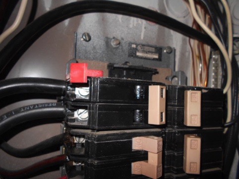
My main panel isn't too strong. It's just at 100A, but I'm looking to upgrade it this summer to 200A.
Today, my house experienced a power outage. Power returned within 10 min, but I didn't get the chance to turn off the 60A breaker connected to the Gen 3 Wall connector.
To my knowledge, the main panel currently does not a whole house surge protection.
May I please find out -
Thank you for any input.
My main panel isn't too strong. It's just at 100A, but I'm looking to upgrade it this summer to 200A.
Today, my house experienced a power outage. Power returned within 10 min, but I didn't get the chance to turn off the 60A breaker connected to the Gen 3 Wall connector.
To my knowledge, the main panel currently does not a whole house surge protection.
May I please find out -
- Electricity came back before I had the chance to flip the 60A breaker. Is there likely to be damage to the Wall Connector? Or is it robust enough to survive the return of electricity?
- A professional installed my Wall Connector and the 60A breaker. They didn't mention anything about installing a surge protector at the main panel. Is a whole home solution mandatory for the G3 Wall Connector?
Thank you for any input.