Glan gluaisne
Active Member
However, "digital communication" is supposed to mean the RF carrier superimposed on the pilot (plus IP packets, XML etc.), but Tesla have long abused it to mean their own version of digital communication where they do a low-bitrate single-ended CANbus over the pilot pin. Originally this was just for superchargers; then the 2nd-generation Wall Connector (the only version sold in Europe) started doing it, apparently for better management of the load sharing, though the WC also has current measuring so it can still load-share with non-Tesla vehicles. Now you tell us that the UMCv2 is also doing it, though less clear what benefit it brings there.
I've done a further test, by modifying the code in my charge point so that it emulates the CP signal I measured from the UMC. The M3 seems to charge fine when awake; next step is to see if this change has any impact on the failure of the car to wake up and accept charge if the CP signal comes up like this when it's plugged in, but in the deep sleep condition. I suspect it may not change anything.
Unfortunately, the longer-form manual suggests it is a supply voltage monitoring device only, and hence doesn't comply with the current 722.411.4.1(iii) (especially is the manual tells you it is self-resetting).
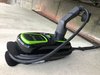
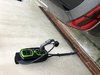
So it's much the same as PodPoint have internally on their units.
It might become permitted under the proposed new 722.411.4.1(iv) for which the public comment period has just finished. It was interesting to read the comments from the manufacturers of Zappi, who think there isn't the headroom to make a supply-voltage based unit operate reliably, particularly with embedded generation potentially raising the voltage inside the installation above limits (even while the supply itself is just within limits - volt drop running in the reverse direction to usual). They favour directly measuring the current in the CPC.
It will be a few months while this plays out.
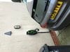
I agree, as it's clear that the module in that device is only monitoring line and neutral. I assumed it was trying to work in the way we've already discussed elsewhere, some months ago, by guessing a fault condition from just doing supply monitoring. The self-resetting problem seems to apply to other charge points, too. Even mine will reset if the power is turned off and back on again, in addition to having to be reset by a switch on the front if it's tripped and the power supply to the unit is still up. I guess I could set a flag in non-volatile memory, and only allow that flag to be cleared by using the manual switch on the front. Should be easy enough to do, but I'm not convinced it's that big a deal, really. Might be just as easy to introduce a deliberate AC leakage current on the supply side under a fault condition (with the contactor open), so that the RCBO feeding the unit trips. The RCM14-03 AC-DC residual current sensor I'm using could easily do this, as it can drive a 12 V relay directly.
Note that the scenario for placing multiple rods 3m apart suggested in the Code of Practice isn't to get Ra<200R in poor ground for a TT earth, rather it's to get down to single figure resistance for placing in parallel with the PME earth in cases where TT isn't acceptable (eg. other PME-earthed metalwork in the vicinity).
It's still bonkers though!
Agreed, but this wasn't the scenario being discussed. The installation was a standard one with a Type B RCBO and earth electrode, so Ra only needed to be <200 Ω for reliability (could be up to 1667 Ω and still just about work OK). In the circumstances described, where a choice was being made between either a Type B RCBO with an earth electrode, or the box made by matt-e, I think I'd opt for the earth electrode solution, as it's been quoted as being £118 cheaper, and has the advantage of being simple and easy to understand by anyone looking at the installation in future.
")