Welcome to Tesla Motors Club
Discuss Tesla's Model S, Model 3, Model X, Model Y, Cybertruck, Roadster and More.
Register

Possible rewiring of my ESS

This site may earn commission on affiliate links.

h2ofun

Active Member
Aug 11, 2020
4,760
1,380
auburn, ca
My current setup has a 400A service, with two 200A breakers. I had this wired into various GW and ATS stuff to feed the two 200A subpanels I have.
The downside to this is the batteries are split, and the generator will not automatically come on if I lose one bank of batteries to one subpanel. At the time,
the installer did not provide any other idea but working with others, it looks technically like I could change all my house and garage into a single GW.
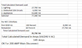
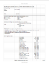
So attached is a load calculation that has been done. Does this look right to folks? Two pictures
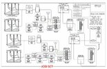
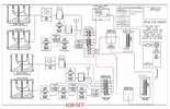
I have also attached my drawings. The one is what I have now with 2 GW's. The second is the proposed wiring change. One question is can I use a 400A subpanel, or do I need to go to a 600A subpanel?
 

Attachments

  • APPROVED_PLANS_v1 fixed post copy-page-003.jpg
    APPROVED_PLANS_v1 fixed post copy-page-003.jpg
    340.9 KB · Views: 95
  • APPROVED_PLANS_v1_2 post copy-page-003.jpg
    APPROVED_PLANS_v1_2 post copy-page-003.jpg
    340.2 KB · Views: 34
  • loads 2.png
    loads 2.png
    16.2 KB · Views: 41
  • loads1.png
    loads1.png
    58.3 KB · Views: 38
So, on the load calc, the largest mini split condenser has an MCA of 32.5A, and for the other 3 you used MCA - 0.25 RLA, as discussed in the other thread?

I'm a bit unclear on why NEC 230.83(A) doesn't split out the HVAC load and count it at 100% (like 230.82 and 230.83(B) do) but instead lumps it in with everything else for the 40% (marginal) factor. If the HVAC is counted at 100% instead of 40%, then that's an extra 53A, putting you at 202A. But you could probably sharpen the load rating on a few of your items to get you down to 200A.

Your proposal basically reduces the grid supply to 200A, and then combines that with all of your inverter breakers (2 * 60A for PV, and 7 * 30A for PWs, or 330A) into a single panel to supply (2) 200A breakers for your (2) 200A load panels. While it would be logical that that could be done with a 400A panel, as the loads are limited to 400A, there's no provision in the NEC for that analysis. It would require a 600A panel as drawn, so that the sum of the ratings of all the electrical sources is no larger than the panel rating.

You could do it with a 400A panel as follows: take one of your 200A generation panel "outputs" and combine it with the 200A from the grid in a splice box to a single 200A feeder. Then your 400A panel has a 200A breaker for that combined feeder, along with the other generation circuits, and that adds up to under 400A of supply to the panel.

The practical difference of doing that vs what you drew is that in the event all the "other generation" circuits are not producing (sun is down, and those PWs are empty), you'd be limited to 200A of total supply to the 400A panel. Vs in your drawing you'd still have 200A from the grid plus the supply from the 200A generation panel. Of course, if your load calc is to be believed, you only really need 200A of supply for all your loads.

Also, on the engine generator configuration, I don't have any direct experience, but I'm sure it's technically feasible to have (2) ATSs, (1) generator, and for the generator to start up if either ATS loses the primary supply, so that ATS can run on generator power, even while the other ATS still has its primary supply and stays on primary power (the grid or the PWs). Whether your particular products support that configuration, I don't know.

And on moving to a single GW, what is the maximum number of PWs a single GW can support?

Lastly, assuming a single GW can support 7 PWs, I think there may be a way to do what you propose in your drawing without any 400A equipment, and with keeping your 2x200A grid connection when running on-grid. It would likely require another ATS for the split PWs to work together when in island (off-grid) mode. But I haven't worked out all the details yet, including how it would interact with your engine generator ATSs.

Cheers, Wayne
I used the MCA directly on all 4 compressors, worse case you implied. So the key question is do they have to be counted at 100%, or can be 40%!!! If it is 100%, then would probably not be worth going any further!
I would have no issue just buying a 600A panel, even though expensive, if can be done, easier.
I asked about the generator ATS stuff. I was told can only have one master, and other is a slave. Made sense, they are not made to wire up with batteries the way I have it.

I was told the GW can support up to 10 powerwalls
So, thanks for the inputs, seems the load stuff with the mini splits is critical to understand
 
I used the MCA directly on all 4 compressors, worse case you implied.
You can go ahead and take the RLA on the 3 smaller ones and subtract 25% of it (times 240V) from the load values for those units. Or cleaner presentation wise would be subtract 25% of the RLA for each unit, and then put in a separate line item for "25% of the largest motor" and put on that line 25% of the RLA of the largest HVAC unit.

So the key question is do they have to be counted at 100%, or can be 40%!!!
Yes, I have a question out about 220.83(A) at mikeholt.com, because counting the HVAC at 40% seems so at odds with 220.83(B) and 220.82, but no responses yet.

If it is 100%, then would probably not be worth going any further!
No, I did the math and came to 202A instead of 149A. And with the correction above, it would probably be under 200A.

I asked about the generator ATS stuff. I was told can only have one master, and other is a slave.
OK, just pointing out that's a limitation of your particular brand and model of hardware, not an inherent generator/ATS limitation. Although I don't know anything about what's commercially available, it could be that at a size/price point for residential use, they all have that limitation.

Cheers, Wayne
 
You can go ahead and take the RLA on the 3 smaller ones and subtract 25% of it (times 240V) from the load values for those units. Or cleaner presentation wise would be subtract 25% of the RLA for each unit, and then put in a separate line item for "25% of the largest motor" and put on that line 25% of the RLA of the largest HVAC unit.


Yes, I have a question out about 220.83(A) at mikeholt.com, because counting the HVAC at 40% seems so at odds with 220.83(B) and 220.82, but no responses yet.


No, I did the math and came to 202A instead of 149A. And with the correction above, it would probably be under 200A.


OK, just pointing out that's a limitation of your particular brand and model of hardware, not an inherent generator/ATS limitation. Although I don't know anything about what's commercially available, it could be that at a size/price point for residential use, they all have that limitation.

Cheers, Wayne
Thanks, look forward to hearing their answer.
When I Talked to tesla, they said there were 3 models of generators that work with the powerwalls that can charge them. They consider this an off line setup, and they do not advertise. Generac is not one of these brands that works. :(
 
When I Talked to tesla, they said there were 3 models of generators that work with the powerwalls that can charge them.
Wow! Finally! Tesla has been denying this possibility for years!

Did you happen to catch what models those are?

My little 2kW portable propane fueled generator is an inverter type, which can be parallel connected with a second generation of the same type. This suggests that they can phase and voltage track with each other, so perhaps they would do so with a PW in backup mode as well. But I'm not (yet) tempted to try it for fear of blowing up either the gen, the PowerWall or both.

Besides, we've had our PW for over two years now, and have not needed to fire up the generator once. So far. But living only a couple miles from the Hayward Fault, I decided to retain the generator and all the associated extension cords. Still my preference would be the ability to use a small gen to top up the PW during a cloudy day outage to provide cheap, quiet overnight backup.
I wrote the names down but cannot find

They were supposed to send me the info on this off grid config, but never got.

It was a much more complicated process to do, like to update fw the house had to be shut off, was really manual, so I can see what they did not want to support.

Give a call and see if you can get the info
 
Which brands are supported?
The generator support was for off-grid systems that never have a grid connection. It included start/stop control, as well as recharging the batteries from the generator. There is no generator to battery charging supported for on-grid systems.

My understanding is new off-grid systems are no longer supported by Tesla. In the past, there were 2 or 3 generators that were supported.
I was told that, but implied, could get if one got lucky. You have the list of the 3 generators they told me.
It really seems like a BIG hassle, and not worth it, unless one had no choice, which 99.999% of us do, with the grid.
 
Thanks, look forward to hearing their answer.
When I Talked to tesla, they said there were 3 models of generators that work with the powerwalls that can charge them. They consider this an off line setup, and they do not advertise. Generac is not one of these brands that works. :(


Does the Generator actually "talk" to the Gateway?

What's stopping you from slapping a bi-directional EV charger on the generator input and shoving suds from an EV into your Powerwalls?
 
FWIW, from Tesla's note on Powerwall Off Grid operation;

"Tesla-Compatible Generators
• Kohler RESA (8kW-20kW)
• Kubota (GL Series)
• Himoinsa (HYW Single Phase Series)
"

All the best,

BG

Available here;
Post in thread 'PowerWall 2 Interface with a Generator'
PowerWall 2 Interface with a Generator


Wait a minute... @Lloyd posted a list of these 3 generators to H2ofun in 2021... is this deja vu?
 
Oh well... if the guy by the lake can't land his bi-directional EVSE to the generator input on the Powerwalls, I guess he can still try to land it upstream of his gateway(s). And somehow coordinate grid charging his Powerwalls at the same time his EVSE is exporting max suds. So then very little EVSE export goes upstream of his PG&E meter.


"The bidirectional charger requires 240 V AC, and it can connect directly to the grid"
 
  • Like
Reactions: h2ofun
I was told these 3 models "talked" to the GW. But as I said, they were going to mail me the info, but did not seem to happen
I went back to some older threads and also found what BG and holey explained. That came from Tesla support for off-grid installations, and required some special configuration by Tesla support during commissioning. Speculation here, but my guess would be that grid tied PW's are fairly sensitive to frequency and voltage variations on the grid, just like solar inverters, so as to go off-line if the grid starts acting funny. But in an off-grid setup, we'd want it to tolerate variations in the generator's output. In any case, that configuration would not be allowed to connect to the grid. That would explain why PW can not support charging from a generator if it also can connect to the grid: Even if the installation prevents doing both at once, the PW can't not change it's grid profile on the fly.

One thread I found (link) has posts from an Australian who actually does charge his grid-connected PW from a generator! He rectified the generator AC into high voltage DC, fed that into a solar inverter (instead of DC from PV panels) which then fed into his house and PW just like his other solar inverters. Probably this should come with a "Don't try this at home!" warning.

In your case, since your generator is for cloudy days when solar is abysmal, you might prefer to switch your existing solar inverters to be fed DC from a generator. But I expect that you'd be the first in the world ever to try that stunt, and your inverter warranties certainly wouldn't help you when they catch fire during the experiment.

So it sound like, for now at least, when it snows, the generator roars.

Back to your original issue, it sure seems that two transfer switches could be run off of one generator. Perhaps you set up the master ATS on the GW which will run out first, so the gen takes over for both GW's at that time. This might be cheaper than re-wiring the panels.

SW
 
FWIW, from Tesla's note on Powerwall Off Grid operation;

"Tesla-Compatible Generators
• Kohler RESA (8kW-20kW)
• Kubota (GL Series)
• Himoinsa (HYW Single Phase Series)
"

All the best,

BG

Available here;
Post in thread 'PowerWall 2 Interface with a Generator'
PowerWall 2 Interface with a Generator

I went back to some older threads and also found what BG and holey explained. That came from Tesla support for off-grid installations, and required some special configuration by Tesla support during commissioning. Speculation here, but my guess would be that grid tied PW's are fairly sensitive to frequency and voltage variations on the grid, just like solar inverters, so as to go off-line if the grid starts acting funny. But in an off-grid setup, we'd want it to tolerate variations in the generator's output. In any case, that configuration would not be allowed to connect to the grid. That would explain why PW can not support charging from a generator if it also can connect to the grid: Even if the installation prevents doing both at once, the PW can't not change it's grid profile on the fly.

One thread I found (link) has posts from an Australian who actually does charge his grid-connected PW from a generator! He rectified the generator AC into high voltage DC, fed that into a solar inverter (instead of DC from PV panels) which then fed into his house and PW just like his other solar inverters. Probably this should come with a "Don't try this at home!" warning.

In your case, since your generator is for cloudy days when solar is abysmal, you might prefer to switch your existing solar inverters to be fed DC from a generator. But I expect that you'd be the first in the world ever to try that stunt, and your inverter warranties certainly wouldn't help you when they catch fire during the experiment.

So it sound like, for now at least, when it snows, the generator roars.

Back to your original issue, it sure seems that two transfer switches could be run off of one generator. Perhaps you set up the master ATS on the GW which will run out first, so the gen takes over for both GW's at that time. This might be cheaper than re-wiring the panels.

SW
The generator is wired to run both ATS and subpanels. It is just under worse case, if the slave batteries die, I just have to turn off the master batteries, and generator triggers both ATS's and I am running everything off the generator. The odds of this happening is me winning the lottery twice :)