jsight
Active Member
I think they just have clear backings to make them look nicer.Is it just me... or do those solar panels look like they have been installed upside down?


You can install our site as a web app on your iOS device by utilizing the Add to Home Screen feature in Safari. Please see this thread for more details on this.
Note: This feature may not be available in some browsers.
I think they just have clear backings to make them look nicer.Is it just me... or do those solar panels look like they have been installed upside down?


") but so far, easy to take apart and reassemble non-destructively. Interestingly, the port heater appears to be right on the board here... A large resistor placed next to each thermistor
but so far, easy to take apart and reassemble non-destructively. Interestingly, the port heater appears to be right on the board here... A large resistor placed next to each thermistor 
They are called bifaciles modules panel i think.I think they just have clear backings to make them look nicer.
Your work will be very usefull for people to come and i would like to thank you for that on their behalf.The Gen4 port arrived. My goodness, Tesla absolutely rules with the "best part is no part" approach. This is the intersection of art and science.
View attachment 769606View attachment 769607View attachment 769608View attachment 769609View attachment 769610
Analysis to come
Oh man. I know nobody should be expected to read back through the past pages of a lengthy thread, but rest assured we are waaaayYYY past thatWouldn't it be possible to compare two part list with a 2018 and a 2021 VIN in epc and order the part that are différent to get CCS support?
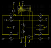
The goal of the work here is to avoid having to buy and install a huge charge port replacement to get CCS. With my plan, the hope is to get it all under $200 (excluding adapter) - about $150 for a readily available Gen4 ECU and maybe around $50 for an adapter harness and any extras. Probably not correct. Everything's a little wonky here. The circuit is like nothing I ever expected nor tested for. Therm-2 is totally disconnected... by design. There's a via there, but it goes nowhere (it's a 2-layer board - every circuit is visible). Almost like left/right channels were planned, but they just bridged them together late in design on Therm-3. Da fuq on picking Therm-2 to depopulate, though? Almost like they wanted to intentionally break compatibility with Gen3. The jerks. Code is hard, etc. ??) -- and what's with Tesla and 45k around here? 69k, I could understand...Try to blow some hot air? to see how its growing/changing?All right. Analysis time.
View attachment 769639
Analysis: ಠ_ಠ
Now, these resistance measurements were taken in-circuit, so the values for the thermistors are ...
So, the resistance being fairly different is ... concerning. I'm probably going to desolder one of each resistor and validate them out of circuit.
The heater is there, though... those resistors are marked - we know they're 33 ohms.
The "cover" appears to bridge pads J6 and J5 (they're big bars on either side of the port). That thus connects an (ahem) 41.3k resistor between INLET_1_CONTINUITY and GND. So, my 10k crap-shoot was off by a fair bit, but it worked (??
Now, what to do... what to do...
edit: I'm also measuring 45k from Therm-3 to GND, so that kinda invalidates all the measurements. The component values simply can't be true if that's the measurement I get. I'm definitely going to have to pull parts to really measure this. Oi. Simple enough though. But I also went back and added highlights to the things I think are wrong - and the rest, I'm reasonably confident on.
Removing R8 and R11 should allow you to measure R9, R10 and R16 in situ.edit: I'm also measuring 45k from Therm-3 to GND, so that kinda invalidates all the measurements. The component values simply can't be true if that's the measurement I get. I'm definitely going to have to pull parts to really measure this. Oi. Simple enough though. But I also went back and added highlights to the things I think are wrong - and the rest, I'm reasonably confident on.
@FalconFour I was just looking at this to find out how to arrange the thermistors if it actually was 10K thermistors on Gen 3 charge port and 45K thermistors on the Gen 4 charge port, checking typical NTC thermistor charts, then remembered something from your previous posts after looking at the charts.All right. Analysis time.
View attachment 769639
Analysis: ಠ_ಠ
Now, these resistance measurements were taken in-circuit, so the values for the thermistors are ...
So, the resistance being fairly different is ... concerning. I'm probably going to desolder one of each resistor and validate them out of circuit.
The heater is there, though... those resistors are marked - we know they're 33 ohms.
The "cover" appears to bridge pads J6 and J5 (they're big bars on either side of the port). That thus connects an (ahem) 41.3k resistor between INLET_1_CONTINUITY and GND. So, my 10k crap-shoot was off by a fair bit, but it worked (??
Now, what to do... what to do...
edit: I'm also measuring 45k from Therm-3 to GND, so that kinda invalidates all the measurements. The component values simply can't be true if that's the measurement I get. I'm definitely going to have to pull parts to really measure this. Oi. Simple enough though. But I also went back and added highlights to the things I think are wrong - and the rest, I'm reasonably confident on.
oh? *thinks* resistive heater, temperature rises, resistance rises, keeps heater from burning out... aka a PTC... *like a ton of bricks hitting my brain* PEE TEE SEE HEATER... NOT NTC...@FalconFour I was just looking at this to find out how to arrange the thermistors if it actually was 10K thermistors on Gen 3 charge port and 45K thermistors on the Gen 4 charge port, checking typical NTC thermistor charts, then remembered something from your previous posts after looking at the charts.
You refer to NTC thermistors being lower resistance at lower temperatures, it's actually the other way around, it is lower resistance at higher temperatures. The nominal resistance is at 25C (77F), at higher temperatures the resistance is lower than nominal, at lower temperatures the resistance is higher than nominal.
That might have thrown you for a loop earlier.
A question:
You posted this schematic of the existing charge port Gen 3 thermistors. Are all 3 of the 10K "resistors" on the top in your schematic thermistors? Do you know the physical location of these thermistors on the charge port?

 NTC is opposite of PTC. Temperature rises, resistance decreases! DUH.
 Yep, that's the key I was messing up. I was actually a bit concerned about that too, because I have some ideas for (metaphorically) gluing the 10k Gen3 thermistors onto the 45k Gen4 (fiddling and twiddling offset resistor values to be "too hot" at the correctly hot temperature, but otherwise not actually reading correctly), but that'd rely on the thermistors still having the same characteristics.
 hope this isn't too scary, lmao)
Does your charge port door locks normally after this 10k solution?oh? *thinks* resistive heater, temperature rises, resistance rises, keeps heater from burning out... aka a PTC... *like a ton of bricks hitting my brain* PEE TEE SEE HEATER... NOT NTC...
THANK YOU for that.
On my (early) Gen3, they're as in this photo - which is as deep as I can seem to disassemble it (white/white, grey/grey = thermistors):
View attachment 769868
No way to really tell exactly where they sit without destructive deconstruction. And BTW, FWIW, this is actually the port I'm trying to get working here. haha (sup Tesla engineers peeping the thread
As for that schematic, ignore it -- that's my current "band-aid" disaster that's got me charging at the moment - but entirely without temperature sensing. It's so far and away from what the correct solution is (now seeing Gen4 for the first time, last night).
Gen3's port looks like just a simple 10k between THERM-1 and GND; THERM-2 and GND (as in photo - no circuit board).
Yes but just... No just...Does your charge port door locks normally after this 10k solution?
Ignore that 10k schematic nonsense! It's all bad. No, it doesn't work, my car is perpetually on fire, my pants are on fire, the earth is on fire and I'm drowning. All because of that 10k nonsense I posted. hahaha Wait'll I get a more proper fix figured out.Too late, too late...) I meant closing instead of locking. The door just stays opened and I have to close it manually.Yes but just... No just...
Closest, safest thing to do is just to leave the harness as it is and "satisfy" that nonexistent cover interlock with (what I now realize is) a 40k~47k resistor most likely. The thermistors are still all wrong but the real solution to that is pending.
Don't do that 22k-10k-10k nonsense I did. Everything is on fire and it will start WW3 if you do.
(My OG 33k-VIN port works totally normally with Gen4... at least as normally as the buggy Gen4 works on new cars. Like new cars, it no longer reopens if the door tries closing on the j1772 adapter though. But of course locking is integral to operation, so lock works fine as well. It's the thermistors I'm seriously concerned about, especially at the limits Tesla pushes these damn connectors...)
What nOoOoOOOooo?! I've heard of issues like that, where it just... quits operating the door properly. Something leads me to suspect that the Gen4 firmware is a hack festival inside. AFAIK, the Gen3 ECU was a totally different architecture of MCU (microcontroller), so switching MCUs means porting the firmware for the new platform... and trying to add new features (like heating). My experience with Gen4 was already soured on new cars with glitchy behaviorThe door just stays opened and I have to close it manually
And now I have it on my 2018, too... haha But it figured its dumbness out and closed shortly after, returned to normal operation. Feels normal to me - it opens, closes, locks, unlocks, LEDs, tap-to-open, RF button-press sensing, all seems to work right.
So that means the THERM-1 and THERM-3 circuits are essentially the same: 100k thermistor in parallel with a 100k resistor. But with the heater circuit, I don't know if you can fake this with just a 50k resistor? Maybe not for THERM-3, but probably okay for THERM-1.Oh god no I messed up
Nah, heater circuit is a total "don't-care". Therm-1 and Therm-3 don't touch it. FWIW the board also gets pretty good ground via the "Gnd" (J4) pokey-pin contacting the charge port ground, which has a thiccccc wire leading to chassis. Pin 8 is thus practically just a decorationSo that means the THERM-1 and THERM-3 circuits are essentially the same: 100k thermistor in parallel with a 100k resistor. But with the heater circuit, I don't know if you can fake this with just a 50k resistor? Maybe not for THERM-3, but probably okay for THERM-1.
Aside from that, there's no common circuit between heaters & thermistors, so no interaction to worry about. (would you believe I've done most of this in mspaint so far? )