I would like to run a new circuit to my garage logically wired as below. This would give me two 120v 20 amp circuits that I need and would give me a 240v 20 amp circuit as well. I would use a double pole breaker so if either side goes they both go. Is there anything wrong with this?


Welcome to Tesla Motors Club
Discuss Tesla's Model S, Model 3, Model X, Model Y, Cybertruck, Roadster and More.
Register
Install the app
How to install the app on iOS
You can install our site as a web app on your iOS device by utilizing the Add to Home Screen feature in Safari. Please see this thread for more details on this.
Note: This feature may not be available in some browsers.
-
Want to remove ads? Register an account and login to see fewer ads, and become a Supporting Member to remove almost all ads.
You are using an out of date browser. It may not display this or other websites correctly.
You should upgrade or use an alternative browser.
You should upgrade or use an alternative browser.
Two 5-20R and one 6-20R on same circuit legal?
- Thread starter Atari2600
- Start date
Should be fine, but I'm not an electrician and you should consult one before doing any wiring. That's an MWBC or multi-wire branch circuit. Breaker needs to be 240V 20A
eprosenx
Active Member
I would like to run a new circuit to my garage logically wired as below. This would give me two 120v 20 amp circuits that I need and would give me a 240v 20 amp circuit as well. I would use a double pole breaker so if either side goes they both go. Is there anything wrong with this?
View attachment 361502
From a practical and safety standpoint I see nothing wrong with this as long as you don’t overload either leg based on what you are plugging in.
I honestly don’t know what code says about having both 240v and 120v receptacles on the same circuit.
As others have pointed out, if you just had the 120v receptacles it would be a multi wire branch circuit. Modern code requires these on a combined handle tie (so 240v breaker).
Now I will call out that there are exceptions in the code for some things when you have just a single receptacle on a circuit. So like GFCI is sometimes not required. In this case I am pretty certain GFCI will be mandated. Also, if you designate that 240v receptacle as an EV circuit it is required to be the only receptacle on the circuit.
So you might be able to call it a receptacle for a table saw.
")
Why not just run a dedicated 240v circuit plus two 120v ones separate?
eladts
Member
I think that a circuit used for EV charging has to be dedicated according to code. This is because EV charging usually maxes out the circuit for a long periods of time.
I guess I could. I am currently operating a Tesla Wall Connector off a temporary 240v 30 amp circuit. I planned on running the mentioned 20 amp circuit along with an 80 amp circuit for the wall connector. I wanted to have a 240v circuit for a backup in case the wall connector went out. I’ve had problems before with chargers and just want an easy backup for the mobile connector.So you might be able to call it a receptacle for a table saw.
Why not just run a dedicated 240v circuit plus two 120v ones separate?
I’m getting a permit, inspections etc so I guess I should run a third line. Wall connector, single 240v, single 120v.I think that a circuit used for EV charging has to be dedicated according to code. This is because EV charging usually maxes out the circuit for a long periods of time.
eladts
Member
I guess I could. I am currently operating a Tesla Wall Connector off a temporary 240v 30 amp circuit. I planned on running the mentioned 20 amp circuit along with an 80 amp circuit for the wall connector. I wanted to have a 240v circuit for a backup in case the wall connector went out. I’ve had problems before with chargers and just want an easy backup for the mobile connector.
I’m getting a permit, inspections etc so I guess I should run a third line. Wall connector, single 240v, single 120v.
If this is a long run from the panel to the garage, you may want to install a sub-panel in the garage and run all three circuits from the sub-panel.
NeverFollow
Active Member
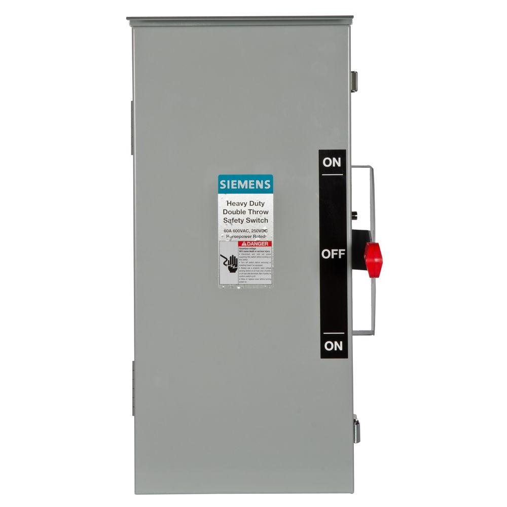
1. If you wan to make it permanent, it would be better to use a double-throw security switch, so there would be no overloading possibility,I would like to run a new circuit to my garage logically wired as below.
This would give me two 120v 20 amp circuits that I need and would give me a 240v 20 amp circuit as well.
I would use a double pole breaker so if either side goes they both go.
Is there anything wrong with this?
as I imagine that your circuit breaker must 20 A, and isolate the 120 V from the 240 V.
I would also recommend using GFCI (Ground Fault Circuit Interrupter) 20 A plugs and circuit breaker.


2. If you wan to make it temporary, for example you want to be able to plug a 12 V battery charger, or a vacuum cleaner...
You could build a DIY extension for that special occasion.
I had some extra wires, so I build this extension that could be useful to have, while I would be careful for not overloading the circuit.
I use a NEMA 14-50 input plug to convert to a NEMA 10-30 receptacle because the TESLA Gen2 portable UMC 14-50 adapter was sold out.
By the same occasion I added two single phase NEMA 5-20 GFCI plugs, as this can be useful.
Also, this was a way to test that the original NEMA 14-50 wall receptacle was correctly wired and grounded,
using a simple single phase GFCI tester.

Here is below the NEMA 14-30 to 10-30 and 5-20 GFCI extension.
I used AWG 10/4 SO for the cord and AWG 14 to wire the 5-20 plugs.
Last edited:
animorph
Active Member
I'm not an electrician either. Surprised none have responded so far. I would think a 240V breaker with only one side overloaded wouldn't trip as fast as when both sides are overloaded, given the two breakers are physically tied together. So a max 240V load and one 120V outlet max load might might cause more of a problem than it should.
eprosenx
Active Member
I'm not an electrician either. Surprised none have responded so far. I would think a 240V breaker with only one side overloaded wouldn't trip as fast as when both sides are overloaded, given the two breakers are physically tied together. So a max 240V load and one 120V outlet max load might might cause more of a problem than it should.
Nah. They will still break at the same speed. If either side trips it takes the other with it. A 240v breaker is two identical 120v breakers with a common trip handle (I believe the common trip is actually handled internally so even if you strap the handle in the on position it will still break).
Vines
Active Member
I wasn't willing to pour through my NEC to figure out why not to do this.
Common sense told me it was a bad idea, especially without a double throw type lockout.
Run a separate 240 v and a 120v circuit is what I would do. Wire, breaker, and labor cost is minimal.
Conceptually your neutral would easily overload, assuming you used both the 120v outlets at near capacity. The return current from a full draw on both L1 and L2 would all come back through the neutral. You could oversize the neutral, assuming it physically fit in the outlets. In my experience "This is not how we do things right" YMMV.
eprosenx
Active Member
I wasn't willing to pour through my NEC to figure out why not to do this.
Common sense told me it was a bad idea, especially without a double throw type lockout.
Run a separate 240 v and a 120v circuit is what I would do. Wire, breaker, and labor cost is minimal.
Conceptually your neutral would easily overload, assuming you used both the 120v outlets at near capacity. The return current from a full draw on both L1 and L2 would all come back through the neutral. You could oversize the neutral, assuming it physically fit in the outlets. In my experience "This is not how we do things right" YMMV.
No. There is no condition here where the neural could be overloaded. This is precisely how a multi wire branch circuit works. It has two 120v circuits sharing one neutral wire. The two circuits are 180 degrees out of phase such that the current on the neutral will cancel if both 120v circuits are loaded the same.
So ironically, if both 120v circuits are at 100% load, the neutral carries no current. If one circuit is at 100% and the other is at 0% then the neutral is at 100%.
If the OP just wants a couple dedicated 120v receptacles to use for woodworking or something that they would never make use of while needing to use the “backup” 240v 20a receptacle for charging then it wold never be an issue from a practical standpoint.
I just don’t know if it is allowed or disallowed by code. I do know that it likely would have to be GFCI on the 120v receptacles since it is in a garage and is not a single receptacle on a circuit. It also could not be designated as an EV receptacle since that would require a fully dedicated circuit.
Used properly I see nothing dangerous about this setup, but again, we should all comply with codes since they exist for a reason. This is just a really weird use case.
If it wasn’t for the code issue I would do it as i planned on having the outlets within 5 ft of each other.
I currently have one outlet in the garage hooked up to my air compressor and rapid charge 20v charger. This circuit is also on the coffee maker inside and on another outlet used for ironing. It also powers the outlets in the master bath used for hairdryers and curling irons. It also drove the outlet on the back outside of the hose. But someone took it out and ran 10 AWG 20 amp to a new one and used outside rated 20 a GFCI.
I currently have one outlet in the garage hooked up to my air compressor and rapid charge 20v charger. This circuit is also on the coffee maker inside and on another outlet used for ironing. It also powers the outlets in the master bath used for hairdryers and curling irons. It also drove the outlet on the back outside of the hose. But someone took it out and ran 10 AWG 20 amp to a new one and used outside rated 20 a GFCI.
Similar threads
- Question
- Replies
- 16
- Views
- 2K
- Replies
- 6
- Views
- 1K
- Replies
- 24
- Views
- 2K
- Replies
- 82
- Views
- 3K
- Replies
- 19
- Views
- 613