Rick,
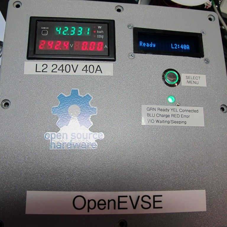
Based on the image you provided, you appear to have a PZEM-004 AC 80-260V 0-100A Meter Module Multifunction Energy Metering AC Power Monitor. I searched a few sites that sell this meter and have found that it is can accept up to 260VAC input. The following link provides the technical information as well as a wiring diagram. https://www.circuitspecialists.com/content/189799/ac004.pdf
Power = Watts = Volts * Amps
So, to meter your load properly, you need to supply the meter with the proper voltage and current. Thus, since you are metering a 240VAC, single phase application, you must provide 240VAC input to the meter.
How to get the 240VAC? First, there is minimal current draw from the meter itself, so I would say that you can use 18 awg or larger with no problem. Make sure the wire is rated for greater than 250VAC.
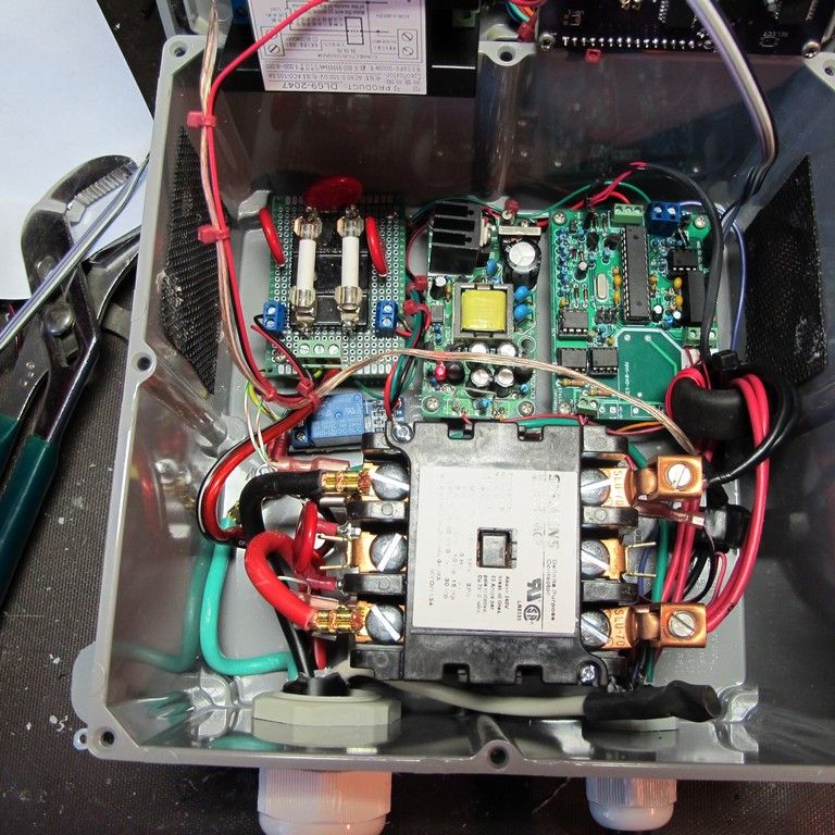
As to where to tap the voltage from, you need to find a way to tie the two voltage sensing wires to the actual L1 and L2 wires that are serving your charger.
As to if the meter needs to be on its own breaker, I would say no, as long as L1 and L2 that you would be connecting to are protected by a breaker.
For safety, I would install an in-line 2 amp fuse on one of the voltage sensing wires where it connects to the meter. This would allow the fuse to protect the meter, just in case something happened.
The following is provided for illustration purposes. Check and follow local codes and consult a licensed electrician
How to tap you voltage sensing wires: 1. Turn the breaker OFF and double check with a voltmeter that there is no voltage present. 2. Find a screw terminal were the L1 and L2 conductors are landed. 3. Loosen the terminals and remove the conductors. 4. Strip approximately 1 1/2" of the voltage sensing wire ends. 4. Twist one wire on L1 and the other wire on L2. 5. Place the conductors back under their respective terminals and hand tighten. 6. Gently pull each wire to ensure that it is secured under the terminal. 7. Connect an in-line fuse module to L1 input on the meter. 8. Connect the the L1 voltage sensing wire to the opposite side of the in-line fuse fuse. 9. Connect L2 voltage sensing wire to the L2 input of the meter. 10. Verify all wiring connections are tight and then turn the breaker on. 11. Verify that the meter energizes. 12. Connect a load to the circuit and verify that the meter is measuring and displaying all values.
Hope this help point you in the right direction.
PLEASE! Do Not attempt this if you are uncomfortable.
Based on the image you provided, you appear to have a PZEM-004 AC 80-260V 0-100A Meter Module Multifunction Energy Metering AC Power Monitor. I searched a few sites that sell this meter and have found that it is can accept up to 260VAC input. The following link provides the technical information as well as a wiring diagram. https://www.circuitspecialists.com/content/189799/ac004.pdf
Power = Watts = Volts * Amps
So, to meter your load properly, you need to supply the meter with the proper voltage and current. Thus, since you are metering a 240VAC, single phase application, you must provide 240VAC input to the meter.
How to get the 240VAC? First, there is minimal current draw from the meter itself, so I would say that you can use 18 awg or larger with no problem. Make sure the wire is rated for greater than 250VAC.
As to where to tap the voltage from, you need to find a way to tie the two voltage sensing wires to the actual L1 and L2 wires that are serving your charger.
As to if the meter needs to be on its own breaker, I would say no, as long as L1 and L2 that you would be connecting to are protected by a breaker.
For safety, I would install an in-line 2 amp fuse on one of the voltage sensing wires where it connects to the meter. This would allow the fuse to protect the meter, just in case something happened.
The following is provided for illustration purposes. Check and follow local codes and consult a licensed electrician
How to tap you voltage sensing wires: 1. Turn the breaker OFF and double check with a voltmeter that there is no voltage present. 2. Find a screw terminal were the L1 and L2 conductors are landed. 3. Loosen the terminals and remove the conductors. 4. Strip approximately 1 1/2" of the voltage sensing wire ends. 4. Twist one wire on L1 and the other wire on L2. 5. Place the conductors back under their respective terminals and hand tighten. 6. Gently pull each wire to ensure that it is secured under the terminal. 7. Connect an in-line fuse module to L1 input on the meter. 8. Connect the the L1 voltage sensing wire to the opposite side of the in-line fuse fuse. 9. Connect L2 voltage sensing wire to the L2 input of the meter. 10. Verify all wiring connections are tight and then turn the breaker on. 11. Verify that the meter energizes. 12. Connect a load to the circuit and verify that the meter is measuring and displaying all values.
Hope this help point you in the right direction.
PLEASE! Do Not attempt this if you are uncomfortable.
Mike, I guess that would make sense. Thanks.
I am not sure how to safely provide 240 V to the meter. Currently, I have a 120 outlet just below the meter with 18 gauge lamp cord plugged into the 120 V receptacle providing power. (I also have a 30 dryer receptacle next to it). Do I bring the L1 and L2 voltage conductors to the ammeter from the panel or the 30 amp receptacle? In either case, what wire gauge is used since the meter draws such little amperage on its own and would it need its own circuit and circuit breaker?
View attachment 182903