Welcome to Tesla Motors Club
Discuss Tesla's Model S, Model 3, Model X, Model Y, Cybertruck, Roadster and More.
Register

P85 Premium Seat Retrofit

This site may earn commission on affiliate links.
I need to update my guide to reflect this, but I need it to be 100% clear. What does the white and red wire connect to?
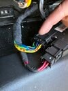
This is the harness from the old seat:
'
qkiBHv81evYGHTkhPstt7jxHytXEX-AQpJDQu3AjS4W1ox4Z1u_hMbd-SsvfgAqEVDa5mhaYg2g7-b1NMZ4gnJGE7-gRgORYcPmrDarJRB--6IHBxJXRQ81HmjGJzsHK4S9RFtB3lvc=w1280

In a nutshell, the White and Red Wires are the two wires which form the sensor which provides a resistance based on the position of the Recline Motor. This is used for seat memory.

Connector P22 is the Recline Motor Harness.

Screen Shot 2023-01-04 at 11.15.49 PM.png


This is the recline motor circuit:

1673139927329.png


Connector P22 is a Delphi 13597381:

1673139979922.png


This is the wiring:

Connector P22 Pin 1 = Old Harness Purple = Motor Positive (the diagram shows this a Motor FWD)
Connector P22 Pin 2 = Old Harness Red = Sensor Positive (diagram shows this as SNS+)
Connector P22 Pin 3 = Old Harness Pink = Motor Negative (the diagram shows this as GND)
Connector P22 Pin 4 = Old Harness White = Sensor Ground Return (diagram shows this as GND)

As indicated by other users, the polarity of the sensor (pin 2 and 4) don't matter. It's merely reading a resistance value.

In my specific case for my seat, this is how the wiring was mapped as below. I know that my wiring colors were different from yours in your guide, so take this color coding below with a grain of salt.

(New) Green w/ Orange Stripe to (Old) Purple
(New) Blue to (Old) Pink
(New) Black with White Stripe to (Old) White
(New) Green with Red Stripe to (Old) Red
 
Just a little recap what can go wrong:
I trusted the seller, and my Gen4 seats looked pristine, however I could not get the airbag lights to disappear. Upon further investigation it turned out that the airbags were removed by the Lithuanian scam sellers. The shop I went to was pretty experienced and managed to transfer the airbags from my old seats into the empty pockets without removing the seats. No airbag lights. So if everything is connected, no programming or recognition of the bags is required. Airbags are just a 2.2 ohm resistance which should be present, and are always re.checked.

Whoever wants to disassemble Gen1 seat back, so it from the front by removing the leather around the sides. There is no entry from the back.

I decided to use crimping with ferules and Wago 221-2411 straight connections. Considered soldering and heatshrink, but decided not to redo everything. Using the wagos is a fullproof way, especially if you have to swap wires. Which I had to do for the seat positions sensors.

Thanks to @VegarHenriksen @xorkid and everyone before them for this great mod and the description and pictures. Now that I have done it I understand how hard it is to snap pictures and dociment it ;)
 
Hi folks

just an update

I’ve done the swap and mostly was per the thread. The main issue I had was I stripped out a head of one t47 Torx bolt. I drilled it out though. Also I’d advise not opening the back of the old seat- you can cut and reconnect most of the wires from the seat base. The only exception on the new seat lumbar - you may need to run a wire to white-pink on only one of the motors connectors as the pink-white wire is jumped between the motors. I used one of the other unused wires in the same motor connector and swapped it over.

The backrest motor wires can be found under the base so no need to cut the connectors in the back rest. even then it is possible to remove the connector as there’s an access hole to push the tab on the connector. See this pic:

D700A72D-9EC4-4DB1-BAF7-7E45C3451CD8.jpeg
 
  • Helpful
Reactions: pilotSteve
Also some guidance on cutting the side seat trims and some part numbers that will help.

To cut the button space out, buy spare seat side trims from tesla for about £10 each, cut these separate to rest of the install. The part numbers are:

1ST ROW LEFT HAND SEAT SIDE SHIELD OUTER - WRAPPED
1083454-00-A
1ST ROW RIGHT HAND SEAT SIDE SHIELD OUTER - WRAPPED
1083458-00-A

good luck finding someone to laser cut ABS as it releases chlorine gas if laser cut using co2 lasers. It also melts or burns/scorches rather than vaporising like wood or acryli.

instead you can use an aluminium template to get a perfect cut using a drill to cut out the bulk and complete using sharp knife and a few grades of sand paper.

where to get the aluminium template: Mercedes use exactly the same switches on the ML w164. The trim (Mercedes part number 313205) is abs with aluminium veneer, this is all you need though:

8D64ADEE-4E57-40CE-A795-079414F76908.jpeg

You only need one for left and right. Cut the Mercedes trim to use as the template. I cut it using tin snips. stick the template down to the trim, using 3M VHB double sided tape, like so:

4C81D177-395F-4756-99F1-DCCFAF7CA524.jpeg
Score the edges of the plastic using a sharp knife and the template edge. Using metal drill bits, drill out the plastic as much as possible:

F0176C33-8468-4DC7-98FF-90D799F0A7B7.jpeg

Cut out the excess using a sharp carpet knife, leave around 0.5mm

7C22AC13-1F6D-4B5F-A7C7-9B179CD8FE54.jpeg
27E07CEF-1E7B-461C-877F-912C11DCC64D.jpeg

Use a range of grit sand paper ( 80 grit, 180 grit, 240 grit then 1200 to polish) to take off the remaining plastic. Then remove the template.

96BCC7D8-E62D-4757-8D22-1839859A0BD0.jpeg

D2976E26-91FD-43BC-BB00-84F28DE03FF9.jpeg


final result is clean, pretty close to a factory finish.

63176C17-6843-40C5-93CB-2CCF707583F0.jpeg
edit: part 2 of my switch odyssey coming soon, once I get it done.
 
I added a Ford /jaguar seat switch for headrest control. It is obscured a bit by the seat belt, but it works. View attachment 660167
I decided to wire up a secondary toggle for handling my headrests, adding another switch as was done by another user here.

I used the BMW E30 series switch.

View attachment 892508
Hey @yangotang @philip295

I have done something similar for headrest control inspired by your efforts using the OEM Tesla switches:

take a look:

other controls:

Any interest in a How-To?
 
Wow. Great work everyone. I’d love to upgrade my 2016 tan interior to white. Hopefully I can do this one day. Looks kinda complicated but doable. Wondering from Start to finish. About how long does this takes to do the front 2 seats. Hopefully someone in the ny area does this upgrade soon.
 
i think i figured out what you did here :) The W164.

Below is the manual from a 2012 Mercedes Benz R class:

1677962385934.png


Footnote 7 shows that headrest height appears only on cars with memory.

The R-Class seat controller is the same footprint (it appears).

I suspect maybe you grabbed the R-class seat controller, desoldered the memory parts, then put it back in the same housing?
 
Wow great work, Yes a post up on this would be really great!

Just out of curiosity, I’m guessing this has something to do with the depopulated pins 1 and 2? This certainly makes it easier and avoids a switch!

I suspect maybe you grabbed the R-class seat controller, desoldered the memory parts, then put it back in the same housing?

I would love to know how you did this with the OEM controller.
OK this sounds like enough demand! hold on to your seat buttons ;)

First you must realise a little about how Car OEMs work. LK makes the seat control buttons for Mercedes before Mercedes decide if they want to have moving headrests in the W164/W251 without memory seats. The LK engineer designs the seat controller to allow for this but no W164/W251 without memory seats with moving headrests was ever built.

The second think to know the difference between electric and electronic - the buttons in the Telsa 2012-2016 seats are from the Mercedes ML164 without memory seats and are designed for 10Amp 12v, as we see in the passenger seat- 12v directly through the switch. The driver side is electronic control via the driver memory module- we will see in my next post how we deal with the driver side very differently.

n.b. we are considering LHD cars in this post- same applies to RHD but mirrored

n.b. we will need to sacrifice two switch controllers for this mod

first open the switch (8 torx small screws (T10/T15?)). there is a screw behind the label.

A328C116-2300-4D90-A4FD-930D6D760F00_1_105_c.jpeg


Desolder the middle 4-way joystick switch from the donor switch:
8C98F2F4-078F-423A-A082-E6573C5EFBB3_1_105_c.jpeg


use a de solder iron (£15)


IMG_5082.JPG


takes some practice to use this but much easier than just a soldering iron

you will have one of these removed from the donor board:

1B4C210D-84AA-4FCF-8C8E-D5F810309C26_1_105_c.jpeg


Then remove the old 2-way joy stick on the new switch:
72C43337-68C2-465F-8887-F6EC5E8F412C_1_102_a.jpeg


solder in the the donor 4-way joystick in place of the old 2-way:

3A40D43A-3E2A-4AF3-BC1F-BD9153C69A5B_1_105_c.jpeg


for the the plastics, you will need one of the retainer clips from the donor switch (the small one on the right):

68A55F4B-F1EB-4DC9-B34C-D5DA42A04106_1_102_a.jpeg


drill out the tilt button retainer on the new switch :

56E1D39E-C00A-4E1E-8191-09C23E38E214_1_105_c.jpeg

(follow the rectangle "template" that is on the switch plastic)

use the same small retainer clip to hold the old button in place:

CAF4260F-6740-4216-8716-82C75D1847D5_1_105_c.jpeg


compare the old switch with the new:


N.B. The proceedure is very different for the driver side as explained before- will upload once I have finished my testing.
 

Attachments

  • 1679141114751.png
    1679141114751.png
    892.9 KB · Views: 46
Awesome! looks like a wild guess was correct.

So since we're on two different geographies i'll use the following terminology to avoid confusion of LH, RH, etc.:
-Driver Side (in a RHD car this is the RH, on a LHD car this is the LH)
-Passenger Side - (in a LHD car this is the LH, on a RHD car this is the RH)

This is the Driver Side:
1679332101593.png


This is the Passenger

1679332137738.png

Switches appear to be pretty much the same electrically from LH and RH.

Observations:
-The Driver's side seat switch missing Pins 2 and Pins 4 on the 4-pin connector (this is written as P16 on the Driver's Side and is P11 on the passenger side). The passenger seat switch without memory has this populated.
-Doing some board level observations these seem to be the +12V and GND power rail feed inputs for each of the individual joysticks.
To accomplish this on the Driver's Side, I think to do this, we'll need to:
-Feed the Seat Height joystick with +12V and GND to directly drive the motor
-Leave the other joysticks alone so they don't interfere with the existing memory seat logic.

I'm guessing @xorkid you're currently investigating cutting traces on the board to make sure you can isolate +12V and GND to only the tilt/recline adjustment?

I'm investigating this now, let's race :)
If we're lucky it looks like we can just depop the solder traces between the top and bottom but I also am bracing for having to cut traces to accomplish this...
I guess the good thing about this is that it's just a two layer PCB
 
  • Helpful
Reactions: pilotSteve
I had a chance to review the schematics and play with the hardware. It looks like cutting traces isn't the best thing to do.

The passenger (non memory) side is simple as you stated.

For the driver's side (memory) -
-The +12V feed is wired, but there are no grounds. This means that the the switch is feeding +12V for whichever direction is desired by the user. +12V is fed to the memory module, and the motor reversing is done in that box.

Best solution I could come up with:

Once you have swapped the joystick per the above you can wire up a dual SPDT relay circuit triggered by either of the +12V poles (from pins 1 and 2 in the seat switch) in order to form the triggers for a motor reversing circuit. You have +12V triggers.

Circuit like this:

Using these SPDT relays: https://www.amazon.com/gp/product/B093GMF6M1/ref=ppx_yo_dt_b_asin_title_o00_s00?ie=UTF8&psc=1


I'll give this a shot and then report back, then provide a wiring diagram.
 
Damn, you guys are figuring a lot since I last looked. Was just curious since y’all digging into seats. Does anyone think it may be possible to retrofit a maybach style recliner? I see the model 3 and y have a powered ottoman that would work great if it could work some how.
 
HELP - I am having an air bag light issue. I originally switched my 2012 p85 seats for 2017 premium seats. Everything worked fine. No air bag light issue. I recently switched to 2017 white seats and I accidentally hook the polarity up wrong in the switch on the forward at sled. Once the air bag light came on I switched the polarity. Air bag light continues to come on. I then put the black seat back in and the light still comes on. That leads me to believe it’s not in my wiring of the seat. Could this be a fuse issue. The seat seams to still function properly. It moves forward and back and tge recline still works . Help please.
 
Confirmed this works.
HELP - I am having an air bag light issue. I originally switched my 2012 p85 seats for 2017 premium seats. Everything worked fine. No air bag light issue. I recently switched to 2017 white seats and I accidentally hook the polarity up wrong in the switch on the forward at sled. Once the air bag light came on I switched the polarity. Air bag light continues to come on. I then put the black seat back in and the light still comes on. That leads me to believe it’s not in my wiring of the seat. Could this be a fuse issue. The seat seams to still function properly. It moves forward and back and tge recline still works . Help please.
I had this same issue and just resolved it.

On the driver’s seat, there is a device on the seat track rail that appears to provide the seat position. Mine was left unplugged triggering the airbag light. Once I repluggrd this in the light went away.
 
Hi all, I have a 2015 MS 70D that I would like to upgrade my Next Gen seats to a new(er) version as mine are too broken in at this point. I'm not comfortable doing this install myself. Does anyone know if any shop in SoCal is willing and capable of doing this?