Welcome to Tesla Motors Club
Discuss Tesla's Model S, Model 3, Model X, Model Y, Cybertruck, Roadster and More.
Register

Retrofit CCS compatibility onto earlier (NA) Model 3 - DIY approach

This site may earn commission on affiliate links.
Status
Not open for further replies.
Well, isn't your car still under warranty? Why not wait for the real retrofit like the EU had? If they find anything wrong with any items during the retrofit, it would be taken care of under warranty? Maybe some items will need to be replaced regardless, but maybe Tesla will just charge a flat fee? I don't know enough about how everything played our across the pond.

Do we think a retrofit is not coming unlike the EU?
😂 I was out of warranty well over a year ago now. I just passed 80k miles this weekend. I drive the hell outta this thing.

My initial goal was to just "get ahead of" the rush of people trying to get the adapter and the retrofit when it comes out (any day now... any? day? now?). Q4 earnings call was like a dump of cold water on anyone hoping Tesla would focus on improving/servicing vehicles though. But as I keep running into blocks, it's increasingly likely that either (a) my car would fundamentally never be compatible with whatever simple ECU upgrade they offer, like they do in EU, or (b) they wouldn't even offer a retrofit if it says it's not enabled.

I also really want to push the conversation forward with those far away from a Tesla service center, so that a skilled and dedicated person/group could know as much as I can share about the process, and do it all without any of Tesla's direct assistance. That's the goal, at least. :)
 
A little new info. A took a quick, basic Google search, and found exactly what I was hoping for: wiring diagrams :)

I took that info, and mapped it out to the pin positions on the charge port ECU.

1643358219626.png


Pin 7, labeled "X688-7 Analog In", is the one that disappeared/moved on the new ECU. It looks to be teed off the charge port Prox pin. That's odd...? Strange for that to be causing this fault. This pin change thus may have nothing to do with the fault at all, and may even be redundant and thus eliminated. Will have to see the new charge port to see if that's the case -- if it's the same as my existing one, that lends further to the theory that the problem is indeed simpler than it seems.

Oh, if this is as simple as a broken ground return (as you can see, there are 3 ground pins in this harness!), this will make my day. Could just be a revision of that charge port cover. @AlexUA - perhaps you've got a car already open to look at that orange closeout cover behind the big orange one? Something about this cover:
1643358473866.png
 
Okay, so perhaps the cover has a switch or ground path back to the ECU? Did you look at the end of the female wire harness? Do you think when you swapped out originally you bumped the cover or a pin-slot or crimp opened in the wire harness?
Nah -- I can/have reliably interchanged Gen4 and Gen3 at least 3 times now back and forth. Each time, a reflash makes Gen4 or Gen3 "work" - but the Gen4 stops at this cover fault, the Gen3 doesn't (it works 100% normally). Could just be that the Gen3 ignores the fault, possibly by programming a workaround for cars of my era with a flawed charge door cover ;) Hey, if you can fix it in software, better than fixing it in hardware, yeah? haha.

Not had a chance to look at the car itself yet (I'm doing all "paper work" here in research to plan the next car-dive). But that should come tomorrow with weekend free time (and excitement with a potential solution)!
 
Hi guys, I do NOT own a Model 3, but I did the CCS retrofit myself for a Model S. So maybe my experience can be helpful. A few remarks:

- In the Model S you need to install an extra wiring harness. Not sure if this would be needed for the model 3, because the extra wiring harness just connects the PLC ECU to the main charger. Most likely there is nothing to do here.

- There is a software step: you need to change the configuration in the gateway, otherwise you'll have a bunch of errors. It seems to me that the Model 3/Y has the same requirement. Looking at the table of gateway keys (that we collected during the glorious hours that anybody had access to toolbox), I found this:

{
"accessId":70,
"codeKey":"plcSupportType",
"content":{
"enums":[
{
"codeKey":"None",
"description":"",
"value":"0"
},
{
"codeKey":"ONBOARD_ADAPTER",
"description":"",
"value":"1"
},
{
"codeKey":"NATIVE_CHARGE_PORT",
"description":"",
"value":"2"
}
]
},
"description":"Type of support for PLC charging standards",
"products":[
"Model3",
"ModelY"
]
},

In my Model S there is a similar key, and the equivalent to NATIVE_CHARGE_PORT won't work, but I got an EU ECU. Nonetheless, I'm sure you'd need to change that, and my guess is that one should set (or add the key) "plcSupportType 1" in internal.dat.

I'm not sure about the other issues that have appeared in this thread, but if you want CCS enabled, most likely you need gateway access (apart from replacing the relevant parts).
 
Interesting point there, @M0rpH3x . I'm not inclined to believe that's the case here, though, because when a Gen4 is installed, it updates fine, it shows CCS support enabled, and ... it just has faults present regarding "charge cover" (not the outside flap, but I'm told it's the cover on the inside). If I were able to clear that fault by satisfying it, I'm certain it'd work. Still not 100% certain that "CCS adapter support" being enabled REALLY MEANS it'd work -- that may be the rub, there -- but it's a good sign.

I couldn't wait tonight, and I tore the car apart already 😂 Weekends just mean no need to drive in the morning! Ha.

1643433400503.png


Here's what I learned.
  • everything lines up with the wiring diagram except for what appears to be a typo on the temp sensor wiring - pins 20 and 14 - both are white, but one is labeled white/violet. The pilot signal pin is white/violet (and also labeled as such, as it is). I chalk that up as a diagram error; the second temperature sensor is simply black & black (no color difference) thus it should be labeled white & white (WH & WH), not wired WH & WH/VT.
  • There is absolutely no sensing wiring that leads to, or interacts with, any part of the charge port covers. None.
  • The ground wire traces a path from the charge port ground pin, T's off to a single green wire to the ECU, then a thick gauge wire leading to a bolt connecting to the car body. Those were all connected.
  • The three ground wires in the wiring diagram are ground-providing terminals, not ground-sensing terminals. They're there to ground the temp sensors, each being a 2-wire thermistor (most likely).
  • This charge port is a CHONKY BOI. my god, I've never seen wire gauges that thick in, ever.
Finally, I got the nerve to pop the plastic melt-rivets off the Gen3 ECU and examine it, too. My conclusion on there is: wow, this is complex; and wow, there doesn't seem to be any provision for a PLC modem on here.

On the Gen4, though, I observed one conclusively useful piece of info: that missing pin is, indeed, completely redundant. In fact, the board has a trace bridging those two pins - just to be sure we know they're redundant:
1643433938211.png


That little jumper trace connects the pin that is no longer present (on the left) with the proximity pin that IS present (on the right). Thus, every pin of the old connector has a place on the Gen4 board, in effect.

I also found this little, uh... engineer's easter egg.
1643434033131.png


ಠ_ರೃ
Bruh, with that trace squeezing between the pads 😂 PCB trace fuse, or ??😀??

Anyway, my next step is to try and dig up a 2020 Model 3 wiring diagram, because the info I had only covered 2018-2019. 🤔 That'll call out any additional pins I'm missing!
 
I found the connector for Oct-2020 to present (Gen4) 👀

1643488953593.png

(Here, annotated with the pins that are actually present on the NA Gen4 ECU (red) vs. potential wires that don't land anywhere (grey))

Compare to old (2018-2020):
1643487842814.png


Interesting additions: CAN bus on 9 and 10 (labeled "GB", so I'm guessing GB/T?), heater on pin 1 and presumably grounded on 13 (pins present), a new thermistor on pin 6 (present - aha! that's that fault, huh), a "continuity" pin on pin 5 (present) and pin 11 (not present), and... 🤷‍♂️ a pin 7 that's present on Gen4 but not in the diagram. (harness positions 7, 8, 14, 15, 18, 19 are all unpopulated in the "connector information" chart).

Interesting omissions: the ground wires for the temp sensors of Gen3 are not present in the 2020+ harness (likely combined in the new plug design), but are present as pins on the Gen4 ECU. I'll double check that those are present. Lends to the theory that compatibility was intended.

BTW, the connector is model AMP 1318917-1, and the crimp pins are AMP 1123343-1.

If that continuity is as simple as a short to ground (I'm going to test its output and see if it's a simple resistor pull-up signal, that can/should safely be grounded), this could be as easy as connecting that pin to ground with a little jumper lead indeed. Then we'll have Gen4 on older cars ;)

(woo!)
 

Attachments

  • 1643486996326.png
    1643486996326.png
    128.5 KB · Views: 169
Last edited:
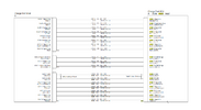
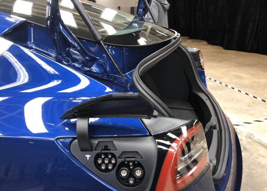
🎺 And now, our feature presentation. 🎥


We're now charging with Gen4 ECU on a mid-2018 Model 3 ;)

I must say, this very much seems "fundamentally incompatible", I don't care what the hell crap Tesla Service is trying to shovel me. Maybe they're not even aware of the significant revision of the charge port between 2018 and late 2020, and most of the calls they deal with are swapping the CCS-stripped Gen4s for non-stripped Gen4's. IDK. Very, very strange. But there is definitely some wiring differences -- despite the physical charge port itself being significantly different, the pins line up enough to just need two minor tweaks.

First tweak: giving the port its continuity sense lead. That's pin 5.
1643496251088.png

I just jammed a wire in there, stripped long to meet the pin. It's a real long channel, and it's a bit flaky a connection... but it's a connection. I'll be buying those crimp pins (detail above) and making something more proper, for sure.

The next trick was: where to put it? Well, I first wanted to test that it was actually a sense line. I shouldn't just go grounding "random" pins. First thing I did was test its voltage to ground: it was 4.77v (so, about 5v). So, I took a thought: typical pull-up resistor is 10k ohms, and if I want to test that, I'll put another 10k on there. That should result in 2.5v DC when the resistor->wire is grounded. Sure enough, it did. And when I did it, the fault immediately cleared. When I released the resistor, "boopboopboop ... boopboopboop", 2 faults came back up. Son of a! That's it!

However, when I grounded the wire straight to the car, it... didn't? clear the fault? So, it doesn't want it to be grounded. Somehow, I landed on a working combination just by guessing at the 10k thing. It's satisfied as long as it sees the 10k resistor there.

1643498491130.png


From there, I just screwed the resistor to a nearby bolt (tacky... should be a ring terminal), and jammed the wire in pin 5. It's happy. And it charges!

But the next issue is to make the thermistors happy. Tes-LAX confirms the fault: none of the charge port sensors are working.
1643496628516.png

Now, assuming the only missing piece is that the grounds are no longer connected on Gen4 (as above: those pins aren't used in the harness anymore), that means I just need to tie them to another ground point. Easy peasy. But for now, it's charging, and it's Gen4, and there's no faults on the screen 😲🤩
 
Last edited:
I must say, this very much seems "fundamentally incompatible", I don't care what the hell crap Tesla Service is trying to shovel me. Maybe they're not even aware of the significant revision of the charge port between 2018 and late 2020, and most of the calls they deal with are swapping the CCS-stripped Gen4s for non-stripped Gen4's. IDK. Very, very strange. But there is definitely some wiring differences -- despite the physical charge port itself being significantly different, the pins line up enough to just need two minor tweaks.
So the retrofit for older cars will likely require a new charge port as well. (Or Tesla won't bother offering a retrofit for the older vehicles.)

I thought that they had a TSB to replace the early unheated charge port with a heated one, but maybe they only did that in cold climate areas?

Edit: the only one I found only says to replace the carrier and latch portion of the charge port: https://static.nhtsa.gov/odi/tsbs/2019/MC-10169040-9999.pdf
 
Last edited:
  • Informative
Reactions: FalconFour
So the retrofit for older cars will likely require a new charge port as well. (Or Tesla won't bother offering a retrofit for the older vehicles.)

I thought that they had a TSB to replace the early unheated charge port with a heated one, but maybe they only did that in cold climate areas?
That, or a variant of the Gen4 charge port ECU that they're not telling us about. Honestly, the latter seems more likely. The only real problems I'm facing are that the ECU is programmed to look for things that don't exist. Maybe the CP ECU and CP harness itself were meant to be replaced together as a unit - which is a real whack situation, given that the charge port itself is so, massively, significantly more complex (of a part, and of a replacement) than the ECU. I would not hope anyone would have to replace the charge port harness. (though, granted, it's still only about an hour's work - involves removing trunk trim as half the work, and the other half of the work is removing a few bolts and snaps).

I've still got an all-new charge port "on order" (which amounts to a pseudo-"service appointment" which is just there for me to collect the charge port, currently scheduled for late Feb), and I still plan on collecting and paying for that, for the info it can provide. Would be really interesting if it ends up being the new (2020+) revision port/wiring -- but the part number matches the old one. Quite odd. Not sure what to make of that... maybe more general not-knowing-what-to-do from the service department.

Next on my to-do list: (1) get those thermal sensors working (I'm likely going to go the route of soldering jumpers on the Gen4 board instead of on the harness), and (2) test CHAdeMO adapter and Supercharging. Stay tuned 🎥
 
New findings, new tests.

The thermistor grounds (pins 14, 18) are ground pins on the Gen4 board, despite not being present in the new (2020+) harness. So, compatibility is there.

The thermistors seem to just be reading +100f more than they should. In Tes-LAX, those numbers slowly increase, just as the charge port normally increases when charging. But the car doesn't seem to mind.

Supercharging works ✅ 100kW at 45% at a v3 station.
CHAdeMO adapter works ✅ the usual crap sandwich though, 44kW and station stopped with a fault, but that's the normal CHAdeMO experience (roll the dice).

I'm almost ready to button the car back up 🥳 I replaced my 10k resistor wire with installing a 10k resistor directly onto the Gen4 board, between pins 5 and 14. So, that's actually quite clean. And since the thermistors already have good ground, that eliminates any need for harness tinkering.

So far, the fix to get Gen4 working (get rid of the "coverOpen" fault, where there is no cover sensor in the "Gen3" charge port) in a "Gen3 car" is just a 10k resistor between pins 5 and 14. As simple as that! And Gen4 now works in old cars.

Yep, that's it: to get CCS compatibility, buy a Gen4 charge port ECU (1537264-00-B for US/NA cars), pop it open, and install a 10k resistor between these pins:
1643509922487.png

(sorry, I didn't get a pic of the actual install I did... so I did my best miming attempt with a photo I had, and mirroring it ;) )

Wait for an update to become available for your car, then de-energize the 12v, swap the ECU, power the car back up (as in that guide), and immediately apply the update -- if you don't immediately apply the update, the car will kill the 12v battery in a very short time (around an hour). When it comes back from the update, you should have no faults, and CCS support should be enabled!

Remember, you're reading advice out of a random internet forum, so responsibility falls on you, etc, etc, etc. Don't be stupid, and try to avoid breaking things. Being a jerk will only make people less likely to want to be helpful in the future. Being not-a-jerk encourages more openness and more cool things. :)
 
Last edited:
Interesting additions: CAN bus on 9 and 10 (labeled "GB", so I'm guessing GB/T?), heater on pin 1 and presumably grounded on 13 (pins present), a new thermistor on pin 6 (present - aha! that's that fault, huh), a "continuity" pin on pin 5 (present) and pin 11 (not present), and... 🤷‍♂️ a pin 7 that's present on Gen4 but not in the diagram. (harness positions 7, 8, 14, 15, 18, 19 are all unpopulated in the "connector information" chart).
If I had to guess, the potential, but unused pins (including continuity inlet 2) have to do with the Chinese market model 3s that have literally two different types of charge connectors, one of them being GB/T as you alluded to.

tesla-model-3-china-dual-ports-gb-t-1024x734.jpg


I would imagine continuity 1 vs continuity 2 is used to figure out which one is actually connected. On vehicles that have only 1 connector, I can't see anything obviously wrong with just using a resistor to pull the pin down. Though rather than soldering onto the PCB, I think I'd just insert a loop of wire between the two pins with a resister soldered and heatshrinked in the middle.
 
  • Helpful
Reactions: FalconFour
On vehicles that have only 1 connector, I can't see anything obviously wrong with just using a resistor to pull the pin down. Though rather than soldering onto the PCB, I think I'd just insert a loop of wire between the two pins with a resister soldered and heatshrinked in the middle.
Well, not quite. There's 2 continuity sensor pin positions, but on the NA board (mine), only one of the pins is populated - and on my June 2018 car (evidently start-of-production to Oct 2020), there's 0 such sensors in the charge port. So it inherently already ignores one, but the missing one (present on Oct 2020 to present cars) needs to be resistor'd to ground. No such opportunity exists for an external jumper (without teeing another wire or using a ring terminal to ground) because pin 14 (the ground I chose) is used to ground one of the two temp sensors. But that ground pin is 0-ohm connected to the board ground plane, common to the whole system, so it's a fair choice.

BTW, what software version are you running for this hardware update?
I'm on 2021.44.30.5 - FSD Beta 10.8.1. I issued a reflash a few times via service mode (to switch back to Gen3 after the flunky service visit, then back to Gen4 today). The same thing can be done with a standard OTA update.

BTW, all the charge port functionality seems to work - the RGB LEDs, the inductive door-press sensor, the RF charge-handle-button to open the door, the door motor, door position, latch motor, latch position... everything in that second connector that wasn't touched, seems to work. Even the behavior/timing/sound seems normal, the same as the Gen3!
 
Last edited:
  • Like
Reactions: wws and Big Earl
There's 2 continuity sensor pin positions, but on the NA board (mine), only one of the pins is populated - and on my June 2018 car (evidently start-of-production to Oct 2020), there's 0 such sensors in the charge port. So it inherently already ignores one, but the missing one (present on Oct 2020 to present cars) needs to be resistor'd to ground.
Yeah so I think what's happening is when Tesla created a model 3 variant with two charge ports (well technically GB/T AC and DC), they made a new charge ECU (i.e gen 4) with the capability of figuring out which of multiple ports is connected. Now this functionality isn't needed on the US and EU ECUs, so those pins for port 2 aren't populated, and they're programmed to ignore the lack of that signal. But I guess in the midst of all this, they still kept the continuity signal for the Type 1 / Type 2 connectors.

Earlier cars had no such pins since there would have never been any variant anywhere in the world that had multiple connectors


No such opportunity exists for an external jumper (without teeing another wire or using a ring terminal to ground) because pin 14 (the ground I chose) is used to ground one of the two temp sensors.
If I'm looking at the board and wiring diagrams correctly, pin 13 seems like a reasonable choice to make a jumper.
 
Last edited:
  • Helpful
Reactions: FalconFour
figuring out which of multiple ports is connected
I think you're getting the function of these pins confused. It's just sensing whether the orange cover inside the car is closed or not (that never, ever gets removed in non-service positions). It's not about detecting a plug being inserted or anything. It's just a service signal.

If I'm looking at the board and wiring diagrams correctly, pin 13 seems like a reasonable choice to make a jumper.
Indeed, it looks like it could be. I didn't take note of that pin when probing, and that could make a good position for an external jumper - unpopulated in both positions in the "Gen3" harness, pin present in both positions on the Gen4 board. I dig it! A bit cleaner than soldering to the ECU board, and maybe a good solution for aftermarket providers. And to that, I'll go place that Digi-Key order for the crimps to test it :)
 
  • Like
Reactions: Bunklung
I think you're getting the function of these pins confused. It's just sensing whether the orange cover inside the car is closed or not (that never, ever gets removed in non-service positions). It's not about detecting a plug being inserted or anything. It's just a service signal.
Okay, so more of a safety device / port presence indicator. I thought it would have to do with plug presence since your original error was something about not being able to tell if the charge cable is plugged in. Nonetheless, I think the only reason for the 2nd one is the GB DC connector (which is not present on US or EU cars - and therefore programmed to be ignored on said cars). 10k resistor is probably a fine substitute, especially if the earlier cars had no means to detect if that orange cover is closed or not anyway.

Only other major difference I'm seeing with the pinouts once accounting for the GB/T stuff and extra grounds is an extra temperature sensor (NTC3)
 
Last edited:
  • Like
Reactions: FalconFour
since your original error was something about not being able to tell if the charge cable is plugged in
Oh nooo! I think I know what you're referring to. I probably wrote too much. That's just a side effect of the unprogrammed/incompatible firmware/disconnected charge port ECU - when it's totally out of the loop, it faults saying it can't tell if the cable is connected or not. Each time though, once programmed/reflashed, it always comes down to two faults: "coverOpen" and "thermistorIrrational". The coverOpen fault was the tricky one that blocks operation. thermistorIrrational seems to be a silent fault / one it ignores.

The key piece of info was Tesla Service informing me that fault had something to do with the orange cover inside the car (and that "thermistorIrrational" was a silent/non-critical warning), at which point I followed the trail that way to figure out what changed between versions. Finding that pin (the "continuity" pin) was the epiphany moment, and it quickly clicked together from there!
 
The thermistors seem to just be reading +100f more than they should. In Tes-LAX, those numbers slowly increase, just as the charge port normally increases when charging. But the car doesn't seem to mind.

So if I'm understanding correctly, these thermistors are present on your existing port as well as (likely) on the newer charge port you have on order. However, they are reading 100F more than expected and likely giving you your nonfatal "thermistorIrrational" error.

I wonder if the newer port uses a different thermistor with a different resistance curve. My concern would be that in typical Tesla fashion Tesla makes this nonfatal error fatal after a later firmware update. I wonder if it's possible to tune the curve in some way to get into a the proper temperature range...
 
Status
Not open for further replies.