There's a couple of technical issues here, at least. The Delta M series inverters have 3 MPPT channels for the M6 and M8 inverters, but just 2 MPPT channels for the M4, M5, and (surprisingly) M10. The OP has 36 panels, so 3 strings on the roof, two of which have to be connected in parallel, probably on the roof. The two strings connected in parallel will likely not do well in MPP tracking during shading.
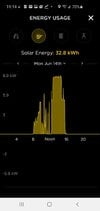
Secondly, the OP posted a solar generation curve that appears to be clipped at 8.8 or 8.9 kW. The M10 max current per MPPT channel is 20A, so we expect clipping in good sun at 34V*12*20A = 8.16kW. The inverter likely clips at a little more than 20A, so it would appear that either 1) the string that isn't connected in parallel is not actually wired to the other inverter MPPT channel, or more likely 2) all three strings are connected in parallel and connected to just one MPPT channel. If 2) is the case, I suppose that the MPPT tracking could get easily confused.
If it were my house, I would get the M Tool app (password is the inverter date code seen on the side of the inverter; activation code is 6532), and query the inverter history to see the voltage and currents in full sun and with the roof partially shaded. I would also use the M Tool app to check the firmware level (I think 3.1.7 is reasonably current) and that the clock is set to PDT as seen on the graphs time axis. All of this has to be done in very close proximity to the inverter. I use phone screen shots to record the graphs.
I can agree with the OP that a SolarEdge system should have been installed in preference to a M10 inverter, or as an alternative, use two Delta inverters so that at least 3 MPPT channels are available. I imagine that showing Tesla repeatedly that system isn't performing correctly will be superior to hectoring them with emails. BTW, I had the best results by writing an email with graphs and pictures, and following that up with a phone call, waiting until I spoke to a live person. The first person you can talk to is not likely to have either the knowledge or agency to do anything, but I found that pleasant persistance would get me to a technical person.