


Hi all,
I have replied on different posts and thought it might be good idea to have a centralised place to put all info on how to read CAN bus from an Arduino UNO.
The advantage of Arduino UNO + CAN BUS MCP2515 is that it's very cheap, you can get all components
for around 10$ if not less.
Ideal if you want to start playing around and I'm conscious that a more flexible setup could be achieved with a raspberry pi which has WIFI and Bluetooth.
Nevertheless if you want an easy&cheap setup this should do pretty fine.
What do you need?
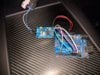
- Arduino UNO
- CAN bus chip MCP2515
- breadboard wires (female - male)
Arduino UNO can be bought on ebay and many other stores.
CAN bus Controller Module: I used the following one MCP2515 also to be found on ebay.
MCP2515 TJA1050 EF02037 CAN Bus Shield Receiver SPI Controller IC for Arduino | eBay
Once you get the hardware, then you can use the following Arduino MCP library written by Fowler.
https://github.com/coryjfowler/MCP_CAN_lib
import the lib in your arduino suite.
The wire configuration :
connect the SPI pins from the CAN bus board to Arduino UNO
CAN board ARDUINO UNO
INT -> pin 2
CS -> pin 10
SI -> pin 11
SO -> pin 12
SCK -> pin 13
GND -> GND
VCC -> 5V
The Can High and Can Low from the module can be attached to the Tesla diagnostic port which is below the big 17' screen, for models 2015 and newer.
CAN H --> x437a pin 18
CAN L --> x437a pin 19
check pinout at x437a diag connector pinout for Tesla Model S
You can easily use the examples already provided in the lib and filter by the message ID you like.
In the attached code you will find a working example of filtering and displaying msg ID 6F2 (Battery Cells Voltage and Temperature).
The output will be on the serial port, so if you are connected with your PC via USB it will display on the serial monitor of the Arduino software.
Code setup:
The CAN module has an 8MHZ oscillator, so the CAN chip needs to be initialize accordingly
CAN0.begin(MCP_ANY, CAN_500KBPS, MCP_8MHZ)
You can change MCP_ANY to MCP_STDEXT and use MCP2515 filters to filter only specified frame IDs (in the source attached I have commented code as an example).
I personally just use code filtering for this easy example, rxId contains the frame id, so i can do my frame handling when rxId == 0x6F2.
Also it's a good idea to set the serial baud rate to 115200.
So far I could read all battery information along with other stuff too, don't seem to miss any frames here.
Havent tried yet to capture data while driving, where most probably there will be more frames on the bus.
other setups to access the diagnostic port and read the CAN bus can be found here
Diagnostic Port Index
enjoy
I have replied on different posts and thought it might be good idea to have a centralised place to put all info on how to read CAN bus from an Arduino UNO.
The advantage of Arduino UNO + CAN BUS MCP2515 is that it's very cheap, you can get all components
for around 10$ if not less.
Ideal if you want to start playing around and I'm conscious that a more flexible setup could be achieved with a raspberry pi which has WIFI and Bluetooth.
Nevertheless if you want an easy&cheap setup this should do pretty fine.
What do you need?
- Arduino UNO
- CAN bus chip MCP2515
- breadboard wires (female - male)
Arduino UNO can be bought on ebay and many other stores.
CAN bus Controller Module: I used the following one MCP2515 also to be found on ebay.
MCP2515 TJA1050 EF02037 CAN Bus Shield Receiver SPI Controller IC for Arduino | eBay
Once you get the hardware, then you can use the following Arduino MCP library written by Fowler.
https://github.com/coryjfowler/MCP_CAN_lib
import the lib in your arduino suite.
The wire configuration :
connect the SPI pins from the CAN bus board to Arduino UNO
CAN board ARDUINO UNO
INT -> pin 2
CS -> pin 10
SI -> pin 11
SO -> pin 12
SCK -> pin 13
GND -> GND
VCC -> 5V
The Can High and Can Low from the module can be attached to the Tesla diagnostic port which is below the big 17' screen, for models 2015 and newer.
CAN H --> x437a pin 18
CAN L --> x437a pin 19
check pinout at x437a diag connector pinout for Tesla Model S
You can easily use the examples already provided in the lib and filter by the message ID you like.
In the attached code you will find a working example of filtering and displaying msg ID 6F2 (Battery Cells Voltage and Temperature).
The output will be on the serial port, so if you are connected with your PC via USB it will display on the serial monitor of the Arduino software.
Code setup:
The CAN module has an 8MHZ oscillator, so the CAN chip needs to be initialize accordingly
CAN0.begin(MCP_ANY, CAN_500KBPS, MCP_8MHZ)
You can change MCP_ANY to MCP_STDEXT and use MCP2515 filters to filter only specified frame IDs (in the source attached I have commented code as an example).
I personally just use code filtering for this easy example, rxId contains the frame id, so i can do my frame handling when rxId == 0x6F2.
Also it's a good idea to set the serial baud rate to 115200.
So far I could read all battery information along with other stuff too, don't seem to miss any frames here.
Havent tried yet to capture data while driving, where most probably there will be more frames on the bus.
other setups to access the diagnostic port and read the CAN bus can be found here
Diagnostic Port Index
enjoy
Attachments
Last edited by a moderator:
