So my setup is pretty simple. But a difficult task with respect to labor.
First Attempt:
Parts/Tools: 18 AWG wire, Crimper tool, 18 AWG Posi-Taps, and T-Tap assortment kit.
Safety:
Although not necessary, but good practice to do when working with electricity - Pop frunk, and disconnect negative terminal from 12v battery.
Process:
I took apart my center console to gain access to the 12v cig lighter. tapping the positive terminal on the cig lighter using the yellow t-tap and blue butt connectors, then feeding the wire down the center console where the air filter meets, I have the two wires split (the same wire where I tapped the positive current flow of the cig lighter.) I used both ends of the split wire to power the passenger and driver footwell lights. The wiring diagram is very simple for the positive terminals on the foot lights. Whichever wire isn’t black, it’s the positive terminal. Mixing the polarity is quite impossible.
Result from attempt #1:
Well, once I seated the negative terminal on the 12v battery again, the lights turned on. A successful DIY for this project. At least in theory. But not the best method in practicality. This setup works well, but the lights only ever turn off if sentry mode isn’t off and isn’t keeping the car awake. The lights only ever turn off if the car enters a deep sleep which is also when the 12v cig lighter turns off and since we’re running the lights off the cig lighter, that will turn off too. But because my OCD wants everything to work perfectly in a practical sense, I wanted the lights to turn off as soon as I exit the vehicle.
Method/Attempt 2 (Practical Method):
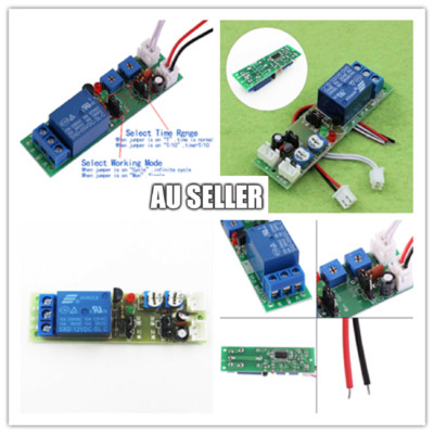
Parts/Tools: Same tools used in attempt #1, but this time, we’re going to be adding a SS relay. You can find a solid state relay on amazon for around $10-15. The one I used for this is:
Relay Used in this project
Process: Again we’re going to go back to the center console here and to the 12v cig lighter. Instead of powering the foot lights with the cig lighter, well be using the cig lighter to power the relay. But why use a relay? Because the aim of this attempt is to have the car turn off the lights as soon as I exit the vehicle, then on when I enter. On the relay, there is a signal input that lights up when a small voltage is applied to that signal input on the relay. We need to figure out which wire to use as the signal input so the relay can turn on/off the footwell lights. The best signal wire I could find was a well hidden wire in the rear vents behind the center console. The cover for the rear vents comes off very easily just pry the upper corners of the rear vents with your hands while the center arm rest is pulled up. It should pop right off. There’s only one wire in the rear vents and depending on the year or build date of your model, it will be taped up with blue tape. Undo the tape and you’ll now see two wires. The color of the wire you want to tap is the tiny brown wire located above the rear air vent outlet. Give yourself room to properly tap this signal wire, and don’t be afraid to pull it out for a better look. Once you’re comfortable with tapping this wire, use the posi-taps to tap the brown signal wire and use the 18 awg wire to wire this across the trim panels down towards your relay. Attach the signal wire to the relay. (Make sure you look at the relay design specifications to determine where which wires go where. Next do the same T-Tap that we did to tap the 12v positive terminal but do the negative terminal on the 12v cig lighter so we can properly power this relay. Since we first used the pos terminal on the 12v cig lighter to directly power the footlights, we can snip the positive terminal right before the two wires split and use the single wire we snipped to power the relay. Then ground the relay using the negative terminal of the 12v cig lighter we tapped. Now we should have one open space on the relay. The other end of the positive wire we snipped will go into the one spot on the relay. Reconnect the 12v battery and power everything back up
Results:
If done correctly, you’ll see the relay light turn on and also the footwell lights. You’ll notice the relay turns off and the footwell lights as well, as soon as you close all doors. Last step is to mount the relay somewhere inside the center console near the cabin air filter and 3m tape it to the car’s body to prevent it from moving. Tidy up the wires so they’re not visible and put the center console back together.
Conclusions:
Ive written this comment in the event of those who are confused on how to wire this up. If you’re confused and need a visual, I’d highly recommend watching this video
Link for disassembly instructions . This fella does a great job at explaining how to take apart the center console and where to find which wires to tap/etc. The only thing I can complain with this video is that he doesn’t explicitly explain where the wires are located, how to splice, etc. You can transition between this thread and video.
Ask if you have any questions, I’d be more than happy to assist!


www.jaycar.com.au