We recently moved to a new house and the Main Panel had plenty of room and a fairly short run to where I wanted to put a Wall Connector.
I was initially going to install a level 2 NEMA 14-50 Outlet and use my spare mobile charger, already purchased Homeline 50A GFCI breaker, and Hubbel 9450. However, I had purchased those items when we lived in an older home with a detached garage approximately 50 feet from the main panel. There, I had 2" underground conduit and purchased THHN wire in separate strands.
That initial thread is here:
 teslamotorsclub.com
However, we moved to a new house out of state and that never got used. Here we are today and below is a list of what I purchased and a few photos of the install process.
1.) Tesla Wall Connector (24') from the forums here - $315
2.) 30 feet of 6/3 Romex from Amazon - $120
3.) Eaton 60A 2 Pole Breaker from Lowes - $20
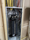
I started by cracking open the panel to see what kind of shape it was in from the builder.
Woofta, what a beauty it was.

Then I ran the 6/3 to the access hole that was left by the builder and pushed it up into the wall.


Next, I measured over on the interior garage wall to the approximate height I wanted the Wall Connector. I knew where the access hole was below, so A simple 1" hole about 2" from the stud I was going to mount the Wall Connector on.
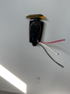
Voila! Grabbed it with a metal pick and pulled it though. I used a Oscillating Multitool to get a little larger hole to pull it through and also a place for the cable clamp to sit into the wall so the Connector body would be flush.

I put a wire nut on the white neutral and left it low and safe in the wall connector body in case we move or replace it with something that requires it. I ended up doing the same thing in the main panel, leaving a wire nut on the neutral white wire and running it long and safely tucking it away.


Here it is mounted, flush and I'm happy. I'l be doing a final drywall coat or two in the spring.
Back downstairs it was time to install the breaker and wire everything up.
Here you can see my neutral with the wire nut, tucked in ground and beginning of the wire organization process to match the original well done work.
View attachment 992774
Final Product, happy to be able to charge at 48A if needed. All in all, 30' was spot on. A little service loop left in the floor and only cutoff about a foot total doing the final trimming on each end.


Total cost: $455.00 USD
Total time: 3 hours
I ended up selling my Mobile Charger, Hubbel 9450A, 55' of THHN wire, and Homeline 50A GFCI for $500.00, so overall it was cheaper to go the wall connector route.
I was initially going to install a level 2 NEMA 14-50 Outlet and use my spare mobile charger, already purchased Homeline 50A GFCI breaker, and Hubbel 9450. However, I had purchased those items when we lived in an older home with a detached garage approximately 50 feet from the main panel. There, I had 2" underground conduit and purchased THHN wire in separate strands.
That initial thread is here:
Detached Garage, Conduit, 14-50, what else am I missing?
Currently wall charging my model 3 on 120V 12A and looking to add a Nema 14-50 plug. We are in Milwaukee, WI - 1950's house, detached garage ~40 feet away from main panel. Main Panel: 100A Service Garage: Load Center with (2) 15A circuits for receptacles & garage door opener. Now, the...
teslamotorsclub.com
However, we moved to a new house out of state and that never got used. Here we are today and below is a list of what I purchased and a few photos of the install process.
1.) Tesla Wall Connector (24') from the forums here - $315
2.) 30 feet of 6/3 Romex from Amazon - $120
3.) Eaton 60A 2 Pole Breaker from Lowes - $20
I started by cracking open the panel to see what kind of shape it was in from the builder.
Woofta, what a beauty it was.
Then I ran the 6/3 to the access hole that was left by the builder and pushed it up into the wall.
Next, I measured over on the interior garage wall to the approximate height I wanted the Wall Connector. I knew where the access hole was below, so A simple 1" hole about 2" from the stud I was going to mount the Wall Connector on.
Voila! Grabbed it with a metal pick and pulled it though. I used a Oscillating Multitool to get a little larger hole to pull it through and also a place for the cable clamp to sit into the wall so the Connector body would be flush.
I put a wire nut on the white neutral and left it low and safe in the wall connector body in case we move or replace it with something that requires it. I ended up doing the same thing in the main panel, leaving a wire nut on the neutral white wire and running it long and safely tucking it away.
Here it is mounted, flush and I'm happy. I'l be doing a final drywall coat or two in the spring.
Back downstairs it was time to install the breaker and wire everything up.
Here you can see my neutral with the wire nut, tucked in ground and beginning of the wire organization process to match the original well done work.
View attachment 992774
Final Product, happy to be able to charge at 48A if needed. All in all, 30' was spot on. A little service loop left in the floor and only cutoff about a foot total doing the final trimming on each end.
Total cost: $455.00 USD
Total time: 3 hours
I ended up selling my Mobile Charger, Hubbel 9450A, 55' of THHN wire, and Homeline 50A GFCI for $500.00, so overall it was cheaper to go the wall connector route.