Welcome to Tesla Motors Club
Discuss Tesla's Model S, Model 3, Model X, Model Y, Cybertruck, Roadster and More.
Register

I'm getting various BMS errors, and my model S won't go into Drive (D) or Reverse (R)

This site may earn commission on affiliate links.
Hey everyone, new to the forum.
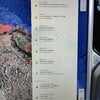
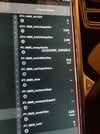
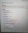
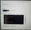
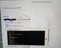
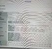
My 2014 Tesla Model S (new to me) is giving me the following BMS errors (see attachment):
- BMS_u008
- BMS_w141
- BMS_w062
- BMS_w033
- BMS_f062
- BMS_f033

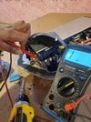
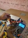
I should mention that the 12v battery isn't holding a charge, so I ordered a new one and it should be here soon. I'm hoping that is what is wrong and that the errors will go away once I replace the 12v battery, but I thought I'd ask the forum gurus and see if anyone has seen these errors before.
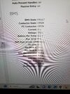
My HV battery (85kw) seems to be fine since it's currently charged at like 85% and it's holding the charge fine.
 

Attachments

  • IMG_20220315_123855.jpg
    IMG_20220315_123855.jpg
    894 KB · Views: 573
  • IMG_20220315_123855.jpg
    IMG_20220315_123855.jpg
    894 KB · Views: 340
These are some pictures I soucred from the service manual, the two 40A fuses are for the AC compressor and the PYC Heater. The lower 20A fuse is for the Battery Heater. What is the other top 20A fuse for? Is that for the 12v +LV supply to the battery?
 

Attachments

  • Screenshot_20240217_225854.jpg
    Screenshot_20240217_225854.jpg
    904.4 KB · Views: 45
  • Screenshot_20240217_225912.jpg
    Screenshot_20240217_225912.jpg
    886.5 KB · Views: 24
Upvote 0
i didn't see insides of gen1 myself but maybe u can trace the large 12v cable to where it goes on the board to HV side n fuse?..
looking at gen2, yeah its smaller one that goes to 12v converter
1708317952531.png

source:

I checked, I could not here any clicks from the back (one click from the front, but that's likey the relays opening and closing).
then it sounds like contactors not closing so no power to dc-dc
might be simply due to present bms codes
I never charged the 12v battery with a trickle charger while charging the main battery. The main battery won't even charge at this point.
no thats not what i meant..
was 12v battery terminals still connected to the car when u were trickle charging?
that one post i linked sounds like that could kill dc-dc... ( i don't know if thats true tho)
Other though, I am debating to pay for the single day use of Toolbox 3. I'm curious if it just needs a hard reset, BMS reset or anything like that to get it up... Do you have any experience with Toolbox 3 that would be useful for testing/Diagnostics?
no experience myself but many ppl bought n used for 1 day
hardest part seems to be to get it connected to the car...
 
Upvote 0
i didn't see insides of gen1 myself but maybe u can trace the large 12v cable to where it goes on the board to HV side n fuse?..
looking at gen2, yeah its smaller one that goes to 12v converter
View attachment 1019724
source:


then it sounds like contactors not closing so no power to dc-dc
might be simply due to present bms codes

no thats not what i meant..
was 12v battery terminals still connected to the car when u were trickle charging?
that one post i linked sounds like that could kill dc-dc... ( i don't know if thats true tho)

no experience myself but many ppl bought n used for 1 day
hardest part seems to be to get it connected to the car...
I checked continuity on the battery heater side that passed. I didn't take out the DCDC converter to check that fuse. Any way to check without taking out the DCDC?

I got toolbox 3 and ran a whole bunch of tests including forcing the HVIL circuit on which all failed. No clicking of the contactors.

Tried thermo diagnostic test, all HV components failed as expected.

Cleared the BMS codes and it came back. Reset the BMS ECU and came back as well.

You can see the attached. There is one option to "install new HV battery" refurbished or new. I am assuming this SHOULD clear any codes on the car. Debating on running this test?

Also I tried to "read" the fuse type, that also failed....

Does this sound like it's the HV Fuse?
 

Attachments

  • 20240219_195934.jpg
    20240219_195934.jpg
    383.2 KB · Views: 23
  • 20240219_201654.jpg
    20240219_201654.jpg
    373.5 KB · Views: 23
  • 20240219_193317.jpg
    20240219_193317.jpg
    582.7 KB · Views: 21
  • 20240219_195532.jpg
    20240219_195532.jpg
    609.7 KB · Views: 20
  • 20240219_195703.jpg
    20240219_195703.jpg
    664.3 KB · Views: 18
  • 20240219_201939.jpg
    20240219_201939.jpg
    401.2 KB · Views: 19
Upvote 0
i don't think its hv fuse, u should get errors with something like sum of bricks is different... can't recall exactly
it seems that u can't even communicate with bms or at least not fully
so quite possible its a wiring or bms is gone bad
error is saying u not getting power to contractors but maybe u also not getting power to bms...

one thing u could try is to lift the car, remove the shield n reach over the Low Voltage connector n try pushing down on it, maybe its not seated all the way...
since toolbox is not helping much u might have to seek more help, this starting to sound like a tough one..
good luck.
Appreciate the support. BMS CAN Gateway communication test passed with Toolbox. So there is communication with the car. I tried to reset the codes and they would just come back.

Please see the attached images. As mentioned about the contactors not clicking, there isn't even a single click and the contactor simply will not turn on at all....

The other system that failed was DCDC Boot CAN Signal monitor failed. Possibly because there is no HV supply to the DCDC.

DCDC ECU Failed to restart as well.

I think to rule out the fuse, I am going to get the main HV Sand Fuse swapped for a HV Hybrid Pyro Fuse.

You mentioned to lift my car and check for low voltage connector. Is there any that supply the HV contactors? If you look at one of the pictures it mentions the HV contactors not having enough 12V supply voltage.

(BMS_w062_SW_Ctr_Pwr_Supply) which states: "The battery management system has detected that a pack contactor is not getting enough power"

Set Condition: The BMS detects that a pack contactor input voltage dropped below the limit threshold

Clear Condition: The BMS detects that both pack contactor input voltage are above the limit threshold.


This makes sense as the last time I drove my 12v battery was dying, it was just boosted enough to drive it back to my home (5km).

What supplies the pack contactors? I think this may lead to something.
 

Attachments

  • 20240220_014226.jpg
    20240220_014226.jpg
    443.3 KB · Views: 16
  • 20240220_013954.jpg
    20240220_013954.jpg
    578.2 KB · Views: 21
  • 20240219_235747.jpg
    20240219_235747.jpg
    529.9 KB · Views: 20
  • 20240219_235847.jpg
    20240219_235847.jpg
    789.2 KB · Views: 20
Upvote 0
Appreciate the support. BMS CAN Gateway communication test passed with Toolbox. So there is communication with the car. I tried to reset the codes and they would just come back.

Please see the attached images. As mentioned about the contactors not clicking, there isn't even a single click and the contactor simply will not turn on at all....

The other system that failed was DCDC Boot CAN Signal monitor failed. Possibly because there is no HV supply to the DCDC.

DCDC ECU Failed to restart as well.
idk how dc-dc is setup but now that u mentioned that, its possible its not booting n preventing bms from closing contactors
i believe anytime any ecu has CAN comm issues u would get MIA error for that unit but maybe dc-dc is communicating on CAN but still not working...
i have an MS with failed 12v (drops to ~5v if unplugged) n if i pw up the car it will charge it to a point that its gets really warm to touch
its possible that ur dc-dc was putting out max amps to keep ur failing 12v charging n poped a fuse inside or just plain failed...
I think to rule out the fuse, I am going to get the main HV Sand Fuse swapped for a HV Hybrid Pyro Fuse.
if u go this route, get Current powered one. Hybrid has 2 li-ion batteries inside that will eventually fail
You mentioned to lift my car and check for low voltage connector. Is there any that supply the HV contactors? If you look at one of the pictures it mentions the HV contactors not having enough 12V supply voltage.
different connectors
1708536517822.png

(BMS_w062_SW_Ctr_Pwr_Supply) which states: "The battery management system has detected that a pack contactor is not getting enough power"

Set Condition: The BMS detects that a pack contactor input voltage dropped below the limit threshold

Clear Condition: The BMS detects that both pack contactor input voltage are above the limit threshold.


This makes sense as the last time I drove my 12v battery was dying, it was just boosted enough to drive it back to my home (5km).

What supplies the pack contactors? I think this may lead to something.
u need to familiarize urself more with how Tesla/EVs are made...
also schematics are free

all 12v circuits are initially supplied by ur 12v battery (before contactors are closed)
once everything checks out (no errors) contactors turn on n u get 12v supplied by dc-dc including charging 12v battery
contactors are also wired thru firemans loop for obvious reasons but they're connected to BMS board
if bms itself powers up with current voltage but not contactors then it could be an issue with the board but i'm no expert

are u sure ur 12v is fully charged?
what Voltage does TB3 seeing?
can u connect a charger so that u have at least 13v n test?
 
Upvote 0
idk how dc-dc is setup but now that u mentioned that, its possible its not booting n preventing bms from closing contactors
i believe anytime any ecu has CAN comm issues u would get MIA error for that unit but maybe dc-dc is communicating on CAN but still not working...
i have an MS with failed 12v (drops to ~5v if unplugged) n if i pw up the car it will charge it to a point that its gets really warm to touch
its possible that ur dc-dc was putting out max amps to keep ur failing 12v charging n poped a fuse inside or just plain failed...

if u go this route, get Current powered one. Hybrid has 2 li-ion batteries inside that will eventually fail

different connectors
View attachment 1020479

u need to familiarize urself more with how Tesla/EVs are made...
also schematics are free

all 12v circuits are initially supplied by ur 12v battery (before contactors are closed)
once everything checks out (no errors) contactors turn on n u get 12v supplied by dc-dc including charging 12v battery
contactors are also wired thru firemans loop for obvious reasons but they're connected to BMS board
if bms itself powers up with current voltage but not contactors then it could be an issue with the board but i'm no expert

are u sure ur 12v is fully charged?
what Voltage does TB3 seeing?
can u connect a charger so that u have at least 13v n test?
So here is what I tried so far in addition to everything else I mentioned above in the thread:

- I took out the DCDC converter, opened it up again (I did this before to replace the AC fuse) and check ALL four fuses. Of course I was able to verify the 3 fuses without taking it apart (AC, PTC and Battery Heater) but I checked the DCDC internal fuse which was the same 20A used for the Batt Heater and all checked out.... I dont know if there are more fuses under that additional cover once you cracked open the DCDC converter.

Can the DCDC converter still be faulty?

- I have not checked the back where you showed the HV and LV
- I have not yet swapped the main Pyro Fuse (yes I ordered the hybrid one which is self powered)

I have a question... So I saw this post from "UrTomas" frin TMC measured the resistance of each of those HC components. He shared:
A/C Comp: 500ohm
PTC: 500ohm
Battery Coolant Heater: 50ohm

Is this verified to be correct?

I don't know the right "ohm" setting to put on the multi-meter but I left it on the "continuity" mode which has the sound to run my resistance check on each. Here are the number I got for mine:
A/C Comp: 1 (no continuity?)
PTC: 525
Battery Coolant: 35

I tried the A/C comp several times and I only get a reading once I had the multi-meter set to "200". But nothing for any of the other settings. Does this mean the A/C comp is the culprit? Before when the A/C fuse was blown I was still able to drive the car with no issues just no A/C.

As for the battery yes I charged it fully first as well during the tests.
 
Upvote 0
I checked continuity on the battery heater side that passed. I didn't take out the DCDC converter to check that fuse. Any way to check without taking out the DCDC?

I got toolbox 3 and ran a whole bunch of tests including forcing the HVIL circuit on which all failed. No clicking of the contactors.

Tried thermo diagnostic test, all HV components failed as expected.

Cleared the BMS codes and it came back. Reset the BMS ECU and came back as well.

You can see the attached. There is one option to "install new HV battery" refurbished or new. I am assuming this SHOULD clear any codes on the car. Debating on running this test?

Also I tried to "read" the fuse type, that also failed....

Does this sound like it's the HV Fuse?
Maybe you can check if 12V power reaches BMS contactors, maybe there is a bad connection to contactors. (Bad wire near fireman's loop?)

It seems that while driving 12V was lost from contactor feed therefore car reported crash error?

Screenshot_20240223_215639_Drive.jpg
 
  • Like
Reactions: brainhouston
Upvote 0
I have a question... So I saw this post from "UrTomas" frin TMC measured the resistance of each of those HC components. He shared:
A/C Comp: 500ohm
PTC: 500ohm
Battery Coolant Heater: 50ohm

Is this verified to be correct?

I don't know the right "ohm" setting to put on the multi-meter but I left it on the "continuity" mode which has the sound to run my resistance check on each. Here are the number I got for mine:
A/C Comp: 1 (no continuity?)
PTC: 525
Battery Coolant: 35

I tried the A/C comp several times and I only get a reading once I had the multi-meter set to "200". But nothing for any of the other settings. Does this mean the A/C comp is the culprit? Before when the A/C fuse was blown I was still able to drive the car with no issues just no A/C.
idk what those values should be or if they even matter but that's not ur problem rn..
u have codes for no contactor power so either no 12v input for contactors or no 12v output from BMS for contactors...
 
Upvote 0
idk what those values should be or if they even matter but that's not ur problem rn..
u have codes for no contactor power so either no 12v input for contactors or no 12v output from BMS for contactors...
Right, the issue is the BMS is thinking that there isn't enough voltage 12V to clear the set conditions, which would close the HV contactors.

I checked to see if there is a resistance reading from the HV +/- and the LV +/-.

Every closed loop (none shorted) circuit should technically show some value ? Correct me if I'm wrong.

The HV side I get a reading. The LV side I get absolutely nothing... Even without the HV side being on (closed HV contactors) the LV side should theoretically be reading the voltage of the 12V. Once it drops below I think 12.3V the the DCDC should request support from the BMS (HV) to provide power. So I would assume that there SHOULD be some resistance reading from LV terminals to indicate nothing is shorted?

I also slightly smell a burnt smell, not sure if that's just how it smells being closed sealed in that box. All 4 fuses are good. I am not sure what's under that cover intop but best not to open that I don't think there would be additional fuses inside.

Could the DCDC go bad with all the fuses still being intact? I assumed that's what that one 20a fuse is for, internal DCDC converter fuse.
 

Attachments

  • 20240224_144007.jpg
    20240224_144007.jpg
    450.9 KB · Views: 18
  • 20240224_143944.jpg
    20240224_143944.jpg
    439.1 KB · Views: 22
  • 20240224_143806.jpg
    20240224_143806.jpg
    405.3 KB · Views: 18
Upvote 0
Maybe you can check if 12V power reaches BMS contactors, maybe there is a bad connection to contactors. (Bad wire near fireman's loop?)

It seems that while driving 12V was lost from contactor feed therefore car reported crash error?

View attachment 1021172
I checked all the fuses that would connect that 12v supply to the contactor. All were good. Fireman's loop was also good.

Yes, the car lost the 12v battery supply while driving since it was really low when I boosted it to drive. Those crash codes should have cleared with all of the tests I ran with Toolbox. Unless, does it have to be removed by connecting to the battery directly to clear the BMS codes.with the Tesla High Voltage Battery Diagnostics software?
 
Upvote 0
Every closed loop (none shorted) circuit should technically show some value ? Correct me if I'm wrong.
That's not how it works..
Output could have a relay or power transistor...
Trying to measure resistance of un-powered complicated circuit with 100s or 1000s of components won't get u a resistance value, most times it'll be 'open' ie infinity or 1 on display...

Unless, does it have to be removed by connecting to the battery directly to clear the BMS codes.with the Tesla High Voltage Battery Diagnostics software?
Toolbox should be all u need IF the problem is fixed which is not, so u can't clear an active code...
 
Upvote 0
That's not how it works..
Output could have a relay or power transistor...
Trying to measure resistance of un-powered complicated circuit with 100s or 1000s of components won't get u a resistance value, most times it'll be 'open' ie infinity or 1 on display...


Toolbox should be all u need IF the problem is fixed which is not, so u can't clear an active code...
Hmmm, okay thanks for the input. Almost at the point where I feel like taking it to the SC for diagnosis... Tried everything I could. Only thing I'm waiting on is for my HV fuse to come in, and will give that a try.

A few other things I wanted to see was what voltage (for 12v) the ECU is reporting to the car under the CAN Viewer.

Other than that I'm stumped that a perfectly working car that only had the issue of a degraded 12v doesn't drive after changing to a new battery. As mentioned before the old 12v worked after charging it manually, the car started and I drove with it. It's definitely something to do with the 12v system or the fact that maybe, the main HV fuse is toast and can't turn on the conractors.
 
Upvote 0
Also, I read a post from another user that had identical codes as me. They changed the 12v Pyro fuse as well that was the difference and it worked for them.

If the 12v pyro fuse blew technically the car wounldt even start right? I did a continuity on mine and it works...
 
Upvote 0
Sorry 3rd post... but before I forget. Why would my DCDC ECU not restart successfully and give errors via Toolbox? Does it rely on the HVIL for power (no right) ... part of me thinks the DCDC is faulty but the fuses say otherwise (all good).

BMS ECU on other hand works.
 

Attachments

  • 20240220_013954.jpg
    20240220_013954.jpg
    578.2 KB · Views: 19
Upvote 0
I checked all the fuses that would connect that 12v supply to the contactor. All were good. Fireman's loop was also good.

Yes, the car lost the 12v battery supply while driving since it was really low when I boosted it to drive. Those crash codes should have cleared with all of the tests I ran with Toolbox. Unless, does it have to be removed by connecting to the battery directly to clear the BMS codes.with the Tesla High Voltage Battery Diagnostics software?

If 12V pyro is activated you don't have 12V on fuse F29 which supplies BMS which supplies the contactors (see screenshot I shared, otherwise check wiring diagram how pyrofuse works).

What I found interesting is that this fault isn't disappearing on it's own when a charged 12V battery is installed (you don't need toolbox to clear it) makes me think there could be an issue with power supply from F29 doesn't reach BMS (so the contactors.)

1708848464167.png


You said you checked continuity of fireman's loop and fuse F29 but do you also have 12V on that fuse and at firemans loop? (pin 1 and 2 need to have 12V all the time)

Next step would be to check power at X035 and X036 (not sure if they are reachable without pulling battery maybe @brainhouston can verify) or maybe you can see if power reaches BMS in tbx3 since you can communicate with it.

Sorry 3rd post... but before I forget. Why would my DCDC ECU not restart successfully and give errors via Toolbox? Does it rely on the HVIL for power (no right) ... part of me thinks the DCDC is faulty but the fuses say otherwise (all good).

BMS ECU on other hand works.

Not sure if they fully integrate gen1 DCDC diagnose functionality into tbx3 since it's obsolete, say for exmple when you bring it to tesla and it's broken they just charge a retrofit to newer system with separate DCDC/hvjb. Also you don't have any errors relating to DCDC so I would not start searching there
 
Last edited:
Upvote 0
If 12V pyro is activated you don't have 12V on fuse F29 which supplies BMS which supplies the contactors (see screenshot I shared, otherwise check wiring diagram how pyrofuse works).

What I found interesting is that this fault isn't disappearing on it's own when a charged 12V battery is installed (you don't need toolbox to clear it) makes me think there could be an issue with power supply from F29 doesn't reach BMS (so the contactors.)

View attachment 1021677


You said you checked continuity of fireman's loop and fuse F29 but do you also have 12V on that fuse and at firemans loop? (pin 1 and 2 need to have 12V all the time)

Next step would be to check power at X035 and X036 (not sure if they are reachable without pulling battery maybe @brainhouston can verify) or maybe you can see if power reaches BMS in tbx3 since you can communicate with it.


Not sure if they fully integrate gen1 DCDC diagnose functionality into tbx3 since it's obsolete, say for exmple when you bring it to tesla and it's broken they just charge a retrofit to newer system with separate DCDC/hvjb. Also you don't have any errors relating to DCDC so I would not start searching there
I finally put everything back together since I took apart the DCDC converter. I checked the voltage across from F29 and surprise! There is absolutely no voltage across from F29!

It's really strange that there still is continuity across it but no voltage reading.

I will start with this and order a new 12V Pyro fuse. Sucks that Tesla won't sell the fuse directly, eBay it is!

Thanks so much to everyone for your support, keeping fingers crossed this gets my car uo and running. Will keep you posted on the results.

I had heard Mercedes sells this fuse as well (1004635-00-a) I could give them a call to see if they have it available.
 
Upvote 0
I finally put everything back together since I took apart the DCDC converter. I checked the voltage across from F29 and surprise! There is absolutely no voltage across from F29!

It's really strange that there still is continuity across it but no voltage reading.

I will start with this and order a new 12V Pyro fuse. Sucks that Tesla won't sell the fuse directly, eBay it is!

Thanks so much to everyone for your support, keeping fingers crossed this gets my car uo and running. Will keep you posted on the results.

I had heard Mercedes sells this fuse as well (1004635-00-a) I could give them a call to see if they have it available.

That's unusual, did you measure continuity of the Pyrofuse dismounted from fusebox? Do you have 12V on pyrofuse terminal? You can bridge pyro manually to check if 12V reaches F29 and error goes away.
 
Upvote 0
That's unusual, did you measure continuity of the Pyrofuse dismounted from fusebox? Do you have 12V on pyrofuse terminal? You can bridge pyro manually to check if 12V reaches F29 and error goes away.
Sorry for the confusion, I got the fuse number mixed.

F93 (Contactor Power Cutoff (Pyrotechnic)) which is the 12v Pyro Fuse has continuity but no 12v across from it. This is what I find extremely strange... Shouldn't there be 12v across this Fuse?

I also check F92 (Contactor Power) and that has continuity measured in the fusebox.

F94 (Battery-DCDC Master Fuse) has continuity measured in the Fuse box.

F29 (10A Contactor Power), checked for continuity and visually inspected. To clarify I did NOT measure the voltage across from this yet. I will do this tonight. I had measured the voltage across from F93 which does not show a voltage readout but has continuity.
 

Attachments

  • Screenshot_20240226_114256_Gallery.jpg
    Screenshot_20240226_114256_Gallery.jpg
    1.8 MB · Views: 18
Upvote 0