Welcome to Tesla Motors Club
Discuss Tesla's Model S, Model 3, Model X, Model Y, Cybertruck, Roadster and More.
Register

I'm getting various BMS errors, and my model S won't go into Drive (D) or Reverse (R)

This site may earn commission on affiliate links.
Hey everyone, new to the forum.
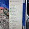
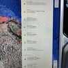
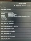
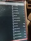
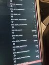
My 2014 Tesla Model S (new to me) is giving me the following BMS errors (see attachment):
- BMS_u008
- BMS_w141
- BMS_w062
- BMS_w033
- BMS_f062
- BMS_f033

I should mention that the 12v battery isn't holding a charge, so I ordered a new one and it should be here soon. I'm hoping that is what is wrong and that the errors will go away once I replace the 12v battery, but I thought I'd ask the forum gurus and see if anyone has seen these errors before.
My HV battery (85kw) seems to be fine since it's currently charged at like 85% and it's holding the charge fine.
 

Attachments

  • IMG_20220315_123855.jpg
    IMG_20220315_123855.jpg
    894 KB · Views: 572
  • IMG_20220315_123855.jpg
    IMG_20220315_123855.jpg
    894 KB · Views: 339
One thing I did note is that there wasn't continuity across from the two pins from F93, which is the resistor that should measure 2.5ohms. This is where that "airbag" like clip plugs into the Pyrofuse.

Sounds like a defective 12v Pyrofuse, I will get a replacement and try this out.

There was a video on this as well where it was mentioned.

As for measuring voltage across from a fuse, yes you are correct 😅, you wouldn't see a voltage drop across two points that have 12v going through (12-12=0). Haha not sure why I mentioned that, this car was just getting to me head!

But I'll report back at the potentially defective F93 fuse, which is interesting how those two pins on the bottom have no continuity. This could be the root cause for all my troubles.
 
Upvote 0
One thing I did note is that there wasn't continuity across from the two pins from F93, which is the resistor that should measure 2.5ohms. This is where that "airbag" like clip plugs into the Pyrofuse.

Sounds like a defective 12v Pyrofuse, I will get a replacement and try this out.

There was a video on this as well where it was mentioned.

As for measuring voltage across from a fuse, yes you are correct 😅, you wouldn't see a voltage drop across two points that have 12v going through (12-12=0). Haha not sure why I mentioned that, this car was just getting to me head!

But I'll report back at the potentially defective F93 fuse, which is interesting how those two pins on the bottom have no continuity. This could be the root cause for all my troubles.

First connect battery negative and firemans loop so car gets live and measure between positive and negative of 12V battery, you should get 12V.

Then measure on fuse F29 and place other wire against negative of battery,

1708971247381.png


If you get 12V (between ground and F29 terminals) the circuit is good (including F92 and F93 pyro) and you need to dig further.

If you don't get 12V you need to go back near the fusebox until you get 12V at some point.
 
  • Like
Reactions: brainhouston
Upvote 0
First connect battery negative and firemans loop so car gets live and measure between positive and negative of 12V battery, you should get 12V.

Then measure on fuse F29 and place other wire against negative of battery,

View attachment 1022172

If you get 12V (between ground and F29 terminals) the circuit is good (including F92 and F93 pyro) and you need to dig further.

If you don't get 12V you need to go back near the fusebox until you get 12V at some point.

Thanks for the input!

I checked the voltage between F29 and the battery ground and I can confirm there is 12.7V. So F29 is good. Also double checked this fuse and its good just to be sure.

I then checked to see if I have 12V from the first responders loop and here are my results. Only the second pin as shown in the picture had 12V. The other pins do not.

1709012559453.png


I think you mentioned that Pin 1 and 2 should have 12V at all times? I am assuming pin 1 is the furthest away from the red lock from the top. That does not have 12v.

So I guess next steps would be to do a visual of the cable if there is spliced cable or any damages.

I also wanted to note, this time I waited for the car to shut down on its own and listened very carefully. At the end I heard 3 consecutive clicks very very faintly from the back.

Please let me know where you think I should investigate next, in the meantime I will look for any breaks from this fireman's loop.
 
Upvote 0
Thanks for the input!

I checked the voltage between F29 and the battery ground and I can confirm there is 12.7V. So F29 is good. Also double checked this fuse and its good just to be sure.

I then checked to see if I have 12V from the first responders loop and here are my results. Only the second pin as shown in the picture had 12V. The other pins do not.

View attachment 1022411

I think you mentioned that Pin 1 and 2 should have 12V at all times? I am assuming pin 1 is the furthest away from the red lock from the top. That does not have 12v.

So I guess next steps would be to do a visual of the cable if there is spliced cable or any damages.

I also wanted to note, this time I waited for the car to shut down on its own and listened very carefully. At the end I heard 3 consecutive clicks very very faintly from the back.

Please let me know where you think I should investigate next, in the meantime I will look for any breaks from this fireman's loop.

There must be pin assignment on the fireman's loop connector (X535) also wire needs to be red according to diagram.

Pin 2 is power for BMS
Pin 1 is power for RCM but think you need to press the brake for that to be live but that is not your issue so I would just leave that.

Screenshot_20240227_071354_Drive.jpg


Next step would be to connect 12V battery and fireman's loop and measure between ground and X950 pin 6 for 12V

Screenshot_20240227_072537_Drive.jpg
 
Upvote 0
There must be pin assignment on the fireman's loop connector (X535) also wire needs to be red according to diagram.

Pin 2 is power for BMS
Pin 1 is power for RCM but think you need to press the brake for that to be live but that is not your issue so I would just leave that.

View attachment 1022417

Next step would be to connect 12V battery and fireman's loop and measure between ground and X950 pin 6 for 12V

View attachment 1022421

Awesome, thanks for the diagram. I will check this tomorrow and report back!
 
Upvote 0
There must be pin assignment on the fireman's loop connector (X535) also wire needs to be red according to diagram.

Pin 2 is power for BMS
Pin 1 is power for RCM but think you need to press the brake for that to be live but that is not your issue so I would just leave that.

View attachment 1022417

Next step would be to connect 12V battery and fireman's loop and measure between ground and X950 pin 6 for 12V

View attachment 1022421
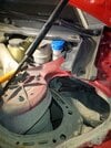
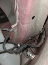
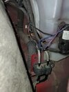
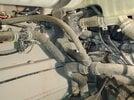
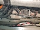
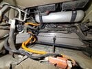
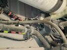
I can't seem to find this connector. I checked everywhere on the LH Side rocker panel area. I took pictures of all the major connections. I think it's the one under the air compressor?
 

Attachments

  • 20240227_185053.jpg
    20240227_185053.jpg
    602.5 KB · Views: 13
  • 20240227_185117.jpg
    20240227_185117.jpg
    363.3 KB · Views: 14
  • 20240227_185146.jpg
    20240227_185146.jpg
    301 KB · Views: 13
  • 20240227_185235.jpg
    20240227_185235.jpg
    523.6 KB · Views: 13
  • 20240227_185343.jpg
    20240227_185343.jpg
    493.9 KB · Views: 13
  • 20240227_185420.jpg
    20240227_185420.jpg
    642.2 KB · Views: 13
  • 20240227_185254.jpg
    20240227_185254.jpg
    492.2 KB · Views: 13
Upvote 0
I am also getting 12v on F53. How about F76?

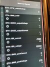
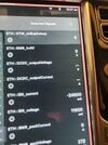
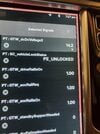
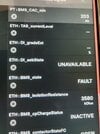
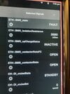
Also using CAN VIEWER here are some signals for the 12v battery and the DCDC.
First is before pressing the brakes, after it's when pressing brakes.
 

Attachments

  • 20240228_002712.jpg
    20240228_002712.jpg
    329.2 KB · Views: 16
  • 20240228_002735.jpg
    20240228_002735.jpg
    364 KB · Views: 19
Upvote 0
I am also getting 12v on F53. How about F76?

Also using CAN VIEWER here are some signals for the 12v battery and the DCDC.
First is before pressing the brakes, after it's when pressing brakes.

So you have 12V on X950 pin 6?

Think you need to check X035 pin 5 and X036 pin 5 but not sure if that's reachable. Maybe connector to BMS isn't seated properly.

Can you check CAN signals for something like 'BMS contactor voltage'?
 
Upvote 0
well 12.2v is already low n after brake press u have 11.9v so that won't be enough
when i had bms errors (contactors open) my X screens shut off at like ~12.0v...
This time again I charged my 12v fully. After pressing the brakes the voltage drops to 12.1v. That should be sufficient.Fully charged my battery shows 12.9v on the multimeter.


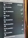
I also checked practically all of the signals on the CAN VIEWER and noticed one thing. The "DI" signals do not report anything at all... not the brake pedal position, throttle position, or parking brake position. After pressing the brake I also get a Service Alert code for "DI_U014_NOT_OK_TO_START_DRIVE" with the message Drive Inverter User Alert: "12v Supply Not Sufficient For Drive".

The signal GTW_dcdcvoltage2 shows 14.2v.

All Signals from the BMS show up, so I suspect nothing wrong with the BMS. Is there something wrong with my Drive Inverter? I think I should investigate the electrical that leads or supplies 12v to the Drive Inverter...
 

Attachments

  • 20240229_193000.jpg
    20240229_193000.jpg
    434.7 KB · Views: 15
  • 20240229_192722.jpg
    20240229_192722.jpg
    388.9 KB · Views: 12
  • 20240229_192428.jpg
    20240229_192428.jpg
    384.2 KB · Views: 12
  • 20240229_191912.jpg
    20240229_191912.jpg
    405.2 KB · Views: 13
  • 20240229_191521.jpg
    20240229_191521.jpg
    305.1 KB · Views: 13
  • 20240229_190739.jpg
    20240229_190739.jpg
    373.4 KB · Views: 12
  • 20240229_190758.jpg
    20240229_190758.jpg
    403.5 KB · Views: 11
Upvote 0
So you have 12V on X950 pin 6?

Think you need to check X035 pin 5 and X036 pin 5 but not sure if that's reachable. Maybe connector to BMS isn't seated properly.

Can you check CAN signals for something like 'BMS contactor voltage'?
I didn't get anything for BMS contactor voltage but the contactors do show open. I am getting DI_U014_NOT_OK_TO_START_DRIVE code which states 12v supply is not enough. I think I should start diagnosing the 12v supply to the DI?
 
Upvote 0
DI not reporting anything is probably due to no 12v to it...
It is strange that u see 14.2v DC-DC while contactor state is open... that is not possible...
That tag must mean something else, like maybe target voltage..
From ur pics, looks like ur at 12.5v with car on n 12.1 with rails on, idk if this is normal drop or not (have u load tested the battery?)
U can always attach a car jump starter to see if that little extra juice will satisfy DI power
But yeah, next logical step is to check 12v on DI LV plug
Yes the only thing that the DI reported was the cruise control toggle on/off. Everything else, it did not show a status for. I would suspect there isn't 12v to going to the DI control unit. I wish I had Toolbox subscription to check the DI ECU, but not worth paying another $260 for a day 😅.

As for the battery, I have not done a load test. When I charged it with my trickle charger, the max it went up to is 12.9v. Should it be higher? I always did suspect if this new 12v was defective since the day I swapped it I had all these issues. Btw the 12.1v you saw with the rail on, was with a 7.5A trickle charger connected. What I'm going to do is I have a second spare battery from a different car, I'm going to charge that fully and connect it to the "boost" the car and see what happens.
 
Upvote 0
Yes the only thing that the DI reported was the cruise control toggle on/off. Everything else, it did not show a status for. I would suspect there isn't 12v to going to the DI control unit. I wish I had Toolbox subscription to check the DI ECU, but not worth paying another $260 for a day 😅.

As for the battery, I have not done a load test. When I charged it with my trickle charger, the max it went up to is 12.9v. Should it be higher? I always did suspect if this new 12v was defective since the day I swapped it I had all these issues. Btw the 12.1v you saw with the rail on, was with a 7.5A trickle charger connected. What I'm going to do is I have a second spare battery from a different car, I'm going to charge that fully and connect it to the "boost" the car and see what happens.
Alright I tested the battery. Brought out my Jeep, hooked up the booster cable and got the voltage with acc rail on to 13.1V. The car is still reporting "low voltage" for both the DI and the Contactors. Only difference again, the DI signals through CAN Viewer do not show anything at all, whereas BMS is fully responsive and shows all of the signals...

Battery at this point I will say is out of the question, it should have cleared when it was reporting 13.1V.

Does anyone have CAN Viewer on their Tesla and con confirm if you can see Pedal position and ect. as shown in my pictures? 5A fuse for the DI is also good (F14). I think next is to test the line down the DI... Any chance the DI got shorted out?

Also, a general question. Lets say the Main Pyro fuse failed, would BMS really report the pack voltage if that happened? How would you know if the main Pyro Fuse fails?
 
Upvote 0
I didn't get anything for BMS contactor voltage but the contactors do show open. I am getting DI_U014_NOT_OK_TO_START_DRIVE code which states 12v supply is not enough. I think I should start diagnosing the 12v supply to the DI?

To my understanding U014 is just a standard error that always pops up when there is no 12V support due to a lack of a working DC/DC

For example, if DC/DC would work and contactors would close and you should still have this error then I would look further into this error, otherwise not. (It's not that when LDU get's no 12V your DC/DC would not work)

If contactor shows open is actually not allowing current to pass see this pic:

Screenshot_20240301_100407_Gallery.jpg


I would focus on w062 and w033 those are uncommon errors.
Plz confirm 12V on X950 pin 6
 
  • Like
Reactions: brainhouston
Upvote 0
To my understanding U014 is just a standard error that always pops up when there is no 12V support due to a lack of a working DC/DC

For example, if DC/DC would work and contactors would close and you should still have this error then I would look further into this error, otherwise not. (It's not that when LDU get's no 12V your DC/DC would not work)

If contactor shows open is actually not allowing current to pass see this pic:

View attachment 1023494

I would focus on w062 and w033 those are uncommon errors.
Plz confirm 12V on X950 pin 6
Thanks for the input. That makes perfect sense.

I am also confirming that there is 12V on X950 pin 6 (RED WIRE) and Pin 7 as well.
1709335359606.jpeg

1709335470108.png

Is there any way I can confirm continuity from X950 (Pin 6 & 7) up to X036 and X035 with out getting to the those two plugs? Such as bridging Pin 6 (male and female) on continuity mode?

I would focus on w062 and w033 those are uncommon errors.
These codes not sure how they showed up after changing the battery (or when I drove it home with a weak 12v battery).

Would you suggest next to look into X036 and X035? Not even sure if this is accessible?
1709335782588.png


Also, again if my main HV Pyro Fuse blew, how would I know? Would BMS still report the pack voltage and what not? Is there any indication if my main pyro fuse blew?
 
Last edited:
Upvote 0
Hey everyone, new to the forum.
My 2014 Tesla Model S (new to me) is giving me the following BMS errors (see attachment):
- BMS_u008
- BMS_w141
- BMS_w062
- BMS_w033
- BMS_f062
- BMS_f033

I should mention that the 12v battery isn't holding a charge, so I ordered a new one and it should be here soon. I'm hoping that is what is wrong and that the errors will go away once I replace the 12v battery, but I thought I'd ask the forum gurus and see if anyone has seen these errors before.
My HV battery (85kw) seems to be fine since it's currently charged at like 85% and it's holding the charge fine.
It looks like "timothypop" had practically the same codes as me... including w062 and w063, All he did was change the 12v and the 12v pyro and it worked...
 
Upvote 0