Welcome to Tesla Motors Club
Discuss Tesla's Model S, Model 3, Model X, Model Y, Cybertruck, Roadster and More.
Register

I'm getting various BMS errors, and my model S won't go into Drive (D) or Reverse (R)

This site may earn commission on affiliate links.
Hey everyone, new to the forum.
My 2014 Tesla Model S (new to me) is giving me the following BMS errors (see attachment):
- BMS_u008
- BMS_w141
- BMS_w062
- BMS_w033
- BMS_f062
- BMS_f033

I should mention that the 12v battery isn't holding a charge, so I ordered a new one and it should be here soon. I'm hoping that is what is wrong and that the errors will go away once I replace the 12v battery, but I thought I'd ask the forum gurus and see if anyone has seen these errors before.
My HV battery (85kw) seems to be fine since it's currently charged at like 85% and it's holding the charge fine.
 

Attachments

  • IMG_20220315_123855.jpg
    IMG_20220315_123855.jpg
    894 KB · Views: 572
  • IMG_20220315_123855.jpg
    IMG_20220315_123855.jpg
    894 KB · Views: 340
Would you suggest next to look into X036 and X035? Not even sure if this is accessible?
this is ur LV plug to HV battery, the one i told u much earlier to check, u can access it only in a way where u can push it down to make sure it has solid connection but u can't unplug it without taking HV pack out...
Also, again if my main HV Pyro Fuse blew, how would I know? Would BMS still report the pack voltage and what not? Is there any indication if my main pyro fuse blew?
Yes BMS has 4 wires connected to both sides of contactors so it knows all voltages whether they're closed or open
I seem to recall that ppl that had HV pyro blown would get 'sum of bricks not equal pack voltage' error (not exact wording)
This is because HV pyro is in series between 14th n 15th module so it will break the chain n BMS will see it
 
  • Like
Reactions: Gtech
Upvote 0
These codes not sure how they showed up after changing the battery (or when I drove it home with a weak 12v battery).
Well, normally you can just drive with a bad 12V battery. In fact when contactors are closed and you pull 12V battery it will stay on and keep functioning. Normally DCDC has more then enough power to keep the car alive

Did you already checked ground point for BMS?
 
Upvote 0
this is ur LV plug to HV battery, the one i told u much earlier to check, u can access it only in a way where u can push it down to make sure it has solid connection but u can't unplug it without taking HV pack out...

Yes BMS has 4 wires connected to both sides of contactors so it knows all voltages whether they're closed or open
I seem to recall that ppl that had HV pyro blown would get 'sum of bricks not equal pack voltage' error (not exact wording)
This is because HV pyro is in series between 14th n 15th module so it will break the chain n BMS will see it
So I guess next would be to take out the HV battery to really check if 12v is getting through all of the harnesses up to that point... That is a lot of work. Lets just say that there is sufficient 12v through the harness, could it be a defective BMS board inside the HV battery? Can it be the contactors shorted out or went bad?

I am still thinking if there is any chance can it also be my DCDC converted not powering on when it is supposed to?
1709405976518.png

Assuming there is 12v going to the contactors to turn on, would the HV Battery BMS send a signal to the DCDC converter to activate based on this wiring diagram, Pin 9 from the DCDC_ENA (enable?). If this is the case should I expect to see 12v from Pin 4 on X040 (signal cable to DCDC)? Or would there be only 12v signal if the contactors are closed? I would assume that would be the correct logic.

Yes BMS has 4 wires connected to both sides of contactors so it knows all voltages whether they're closed or open
So I would say there isn't a way to know for sure if the main pyro fuse is burnt as the BMS can still report all of its BMS signals such as pack voltage?
 
Upvote 0
Well, normally you can just drive with a bad 12V battery. In fact when contactors are closed and you pull 12V battery it will stay on and keep functioning. Normally DCDC has more then enough power to keep the car alive

Did you already checked ground point for BMS?
Makes sense, if it supplies the 12v with approx. 14v of continuous power then yes it should be enough to take over. This is why I am questioning could it simply be a bad DCDC converter? I copied a diagram above from the HV BMS to the DCDC, I am not sure if that is what signals it to enable after contactors are closed or before contactors are closed?

Did you already checked ground point for BMS?
I checked the two ground points on the LH and RH rails under the frunk. Both of which are good.
I have not checked the following:
1709406904424.png

1709407254857.png

If this ground point were to be faulty, I would assume that the BMS would not report readings?
 
Last edited:
Upvote 0
Makes sense, if it supplies the 12v with approx. 14v of continuous power then yes it should be enough to take over. This is why I am questioning could it simply be a bad DCDC converter? I copied a diagram above from the HV BMS to the DCDC, I am not sure if that is what signals it to enable after contactors are closed or before contactors are closed?


I checked the two ground points on the LH and RH rails under the frunk. Both of which are good.
I have not checked the following:


If this ground point were to be faulty, I would assume that the BMS would not report readings?

Agreed but if BMS can't turn on contactors and proper 12V is provided it could also be a bad ground.


With your toolbox session BMS says it doesn't have enough input power to create a voltage for HVIL and suggest to check input voltage from first responder loop.
BMS_w062, BMS_w033, BMS_f062, BMS_f033 tell us there is no 12V input for BMS to provide 12V for contactors

So all issues are pointing to input voltage for BMS.

It's also worth noticing that you can talk to BMS, read values etc but it's still complaining about missing 12V power for contactors.
Also if your DCDC was failing and you keep the car supplied with 12V+ from an external power source I'm sure car would be able to turn on contactors.

Another strange thing is that with no power going to contactors which is equal to a snapped first responder loop it's impossible to drive the car which makes me think maybe there are multiple issues going on here.

Keep in mind DCDC only can work with closed contactors so that's the first main thing to worry about.

Did you tried resetting GTW by changing tire size 19->21 while under external power supply? (MCU1 only) it's a long shot but it will only take a few minutes.
 
Upvote 0
this is ur LV plug to HV battery, the one i told u much earlier to check, u can access it only in a way where u can push it down to make sure it has solid connection but u can't unplug it without taking HV pack out...
Is this located from the inside of the car under the rear seat or carpet? I can try to push it down just wanted to know how to access this. I want to try to push these LV rapid mate splitters in. Can I also access these under to car to push it in more?

Also, just to confirm for sure it's the 12v supply to the contactors, I purposely removed the 10A F29 out to see if any additional errors pop up. Nothing else that was new came, so I guess yes the contactors truly do not have 12v somewhere down past X950...

tell us there is no 12V input for BMS to provide 12V for contactors
Yes I agree. Is there any chance the internal bms board has a fault internal to the battery?
Keep in mind DCDC only can work with closed contactors so that's the first main thing to worry about.
This makes sense. I ended putting my wheel back on the DCDC since I don't that's the issue. Problem was I had my car right against the right side wall in my garage it was a tight space!

Did you tried resetting GTW by changing tire size 19->21 while under external power supply? (MCU1 only) it's a long shot but it will only take a few minutes.
Yes I tried this no luck...
also be a bad ground
I was looking for the bms ground. Is this near the rear left quarter panel. I took the wheel off and the wheel well liner out, could not find it. I am assuming maybe it'd inside the car. Mostly if ground points are inside they are often good since they are protected from the elements.

Also a strange observation, now my DI is showing signals where it didn't before... before it only showed cruise control signal on/off, now it shows everything else but cruise control signal...
 

Attachments

  • 20240302_172055.jpg
    20240302_172055.jpg
    412.8 KB · Views: 18
  • 20240302_172449.jpg
    20240302_172449.jpg
    383.7 KB · Views: 19
  • 20240302_171843.jpg
    20240302_171843.jpg
    220.9 KB · Views: 11
Upvote 0
So this time, I removed the back seat cushion to get access to the grommet that these wires lead to the LV cable, and to have access to X976 Pin 3 (Contactor Power Output).

1709531209495.png


What I did was I back-probed Pin 3 from X976 to ground to see if I would get 12v. I did not, I was only getting 3.77V out from there.

So now I think there are 3 options left here:
1. The 12v supply through the LV Rapid Mate connector is frayed/not seated properly.

2. The ground for BMS is corroded

3. There is an internal fault in the battery (BMS board, contactors?)

I was trying to locate the ground for BMS G721 but the location diagram is not clear...

1709531486551.png

Can someone help point out where it is? If it's internal inside the car it's very unlikely to be corroded.

I also ran my endoscope down the grommet where the BMS 12V supply goes through to see if the rapid mate was seated. I couldn't tell. Posted those pictures.
 

Attachments

  • 20240303_2349026.png
    20240303_2349026.png
    1.4 MB · Views: 10
  • 20240303_2341004.png
    20240303_2341004.png
    1.8 MB · Views: 9
  • 20240303_2336040.png
    20240303_2336040.png
    1.7 MB · Views: 15
  • 20240303_2336036.png
    20240303_2336036.png
    1.7 MB · Views: 10
  • 20240304_003006.jpg
    20240304_003006.jpg
    184 KB · Views: 12
  • 20240304_002944.jpg
    20240304_002944.jpg
    502.8 KB · Views: 14
Upvote 0
1. The 12v supply through the LV Rapid Mate connector is frayed/not seated properly.

2. The ground for BMS is corroded

3. There is an internal fault in the battery (BMS board, contactors?)

Think so yes, measuring in X035 X036, check connectors, check ground or maybe BMS

I was trying to locate the ground for BMS G721 but the location diagram is not clear...

1709569385731.png

So this time, I removed the back seat cushion to get access to the grommet that these wires lead to the LV cable, and to have access to X976 Pin 3 (Contactor Power Output).

Contactor output in wiring diagram is for FC contactors which are for fast charging and are in rear junction box so not internally in the battery pack.

Internal battery pack (so after X035 and X036) is not in wiring diagram.

Can you try backprobe X950 to see if you still have 12V? (with all connectors connected) Sometimes voltage can drop while measuring connected
 
Last edited:
Upvote 0
Can you try backprobe X950 to see if you still have 12V? (with all connectors connected) Sometimes voltage can drop while measuring connected
I tired this before with everything connected and I am still getting more than 12v...
check ground
Thanks for the diagram, the ground was exactly where you posted it under the carpet liner. I checked the ground and interestingly the person who assembled my car did a poor job, The rubber floor lining was jammed in between the ground and the two ground lugs. The bolt was also very loose. This is how it looked:
1709615360198.png

1709615403203.png


1709616353711.png


It still did not change the results... First test I removed ONLY the GDG01 ground and these were the errors: (I kept the BMS ground plugged in)

1709615522289.png


Second test, I then removed ONLY the BMS ground GDG02 and only the original errors stayed, meaning removing the BMS ground had NO IMPACT on the original codes! (I also checked continuity of the BMS ground with it removed to see if there was continuity, yes there still was continuity)

1709615676441.png


Also, something new... I may have accidently pulled on the wires going to the battery from the gromet

1709615850630.png


OR after the "fixed" ground, BMS no longer reports any CAN signals that it did before aside from Pack voltage...
1709615915690.png


I made sure ALL of the connectors were back the way there were... Can I safely say now, that the connection to the BMS (LV Rapid Mate) is defective or not seated properly? Has this ever happened before to anyone?
 
Last edited:
Upvote 0
Also another question, I removed the BMS 5A fuse to see what happens as expected all BMS codes don't show up (nothing reported from BMS as expected) BUT the GTW_W405_12VNOTSUPPORTED stays! Is this my issue? What exactly is this code?

If there is no HV available due to errors that prevents closing contactors then there is definitely no 12V support. Error W405 will not go away untill HV is restored.

Could be BMS also uses ground from battery casing as a sort of reductant ground but I don't know for sure
 

Attachments

  • Screenshot_20240306_210554_Drive.jpg
    Screenshot_20240306_210554_Drive.jpg
    223.6 KB · Views: 20
Upvote 0
If there is no HV available due to errors that prevents closing contactors then there is definitely no 12V support. Error W405 will not go away untill HV is restored.

Could be BMS also uses ground from battery casing as a sort of reductant ground but I don't know for sure
Okay understood thanks!

Just an update, I tried to wiggle the cables back in and reset the bms signals now all of them show how they did before (maybe it didn't show when I removed the BMS ground?)

Anyhow that's all good now, again getting 12V all the way up to X950. I checked continuity on the fireman's loop Pin 2 to Pin 4 and there is NO continuity... there is 12v at Pin 2, but no continuity. Does that mean for sure there is a short/break down the line of the contactor power possibly the LV Rapid Mate?

I would assume even with a bad BMS/Contactors there should be some resistance reading or continuity showing?

Plus BMS shows all signals.
 

Attachments

  • 20240306_235159.jpg
    20240306_235159.jpg
    319.5 KB · Views: 18
Upvote 0
Just a quick question, I have now ordered a used BMS board (will need to program with toolbox) and two used contactors. Just waiting for parts to arrive.

Is there anything else I should look out for when I perform further Diagnostics on my car once the HV is dropped?

This is what I plan to do:
1. Remove HV battery and change to pyro fuse
2. Inspect the X035 and X036 connectors and check for 12v power to contactors. If I get 12V, and it looks like it's properly seated on the plastic holder I'll proceed to the next step.
3. Open up the side of the battery with the BMS board and contactors. This seems very difficult to remove that cover.
4. Remove the contactors and BMS board, and replace with new ones.

Is there anything else you would recommend that I do before or during inspection?

Did you already tried to re-seat connectors X035 X036 with pack still in the car?

Second thing I would do is indeed remove pack and inspect/measure X035 X036 for contactor power and grounds. If all is good (also no moisture or oxidation) proceed to open pack if you can find something but keep in mind to use proper equipment/procedures, 400V can be deadly.

See if 12V contactor power from X035 X036 can reach BMS or maybe a loose connector somewhere
 
Upvote 0
Did you already tried to re-seat connectors X035 X036 with pack still in the car?

Second thing I would do is indeed remove pack and inspect/measure X035 X036 for contactor power and grounds. If all is good (also no moisture or oxidation) proceed to open pack if you can find something but keep in mind to use proper equipment/procedures, 400V can be deadly.

See if 12V contactor power from X035 X036 can reach BMS or maybe a loose connector somewhere
Just an update, I finally dropped the pack off the car and tested the connections of X035 and X036. I am indeed getting 12v at pin 5 for both (also tested pin 2) and the grounds are all good!

At this point, I put the pack back into the car... I was going to take it a part to swap the contactors and BMS board but the replacement board I bought off eBay was damaged.

What are your final thoughts? It's likey thr BMS board?
 

Attachments

  • 20240330_222414.jpg
    20240330_222414.jpg
    292.1 KB · Views: 11
  • 20240330_213844.jpg
    20240330_213844.jpg
    376.2 KB · Views: 12
Upvote 0
Just an update, I finally dropped the pack off the car and tested the connections of X035 and X036. I am indeed getting 12v at pin 5 for both (also tested pin 2) and the grounds are all good!

At this point, I put the pack back into the car... I was going to take it a part to swap the contactors and BMS board but the replacement board I bought off eBay was damaged.

What are your final thoughts? It's likey thr BMS board?

I would love to see an internal wiring diagram from the HV battery internals but I think you need to trace the 12V and if it goes to BMS yes it could be faulty. It's not something that goes bad often.

The fault literally says lost contactor power while driving and will be gone when the issue is restored


BMS_f033_SW_Crash
The Battery Management System (BMS) will trigger this alert when it senses a loss of contactor power while the contactors are closed. The BMS assumes that it could be because the pyro fuse on the contactor power supply signal blew during a crash.

This may trigger while a vehicle is in Service and the contactor power supply loop has been pulled.

BMS_f062_SW_Ctr_Pwr_Supply
The Battery Management System (BMS) has detected that there is a power supply issue with the contactor.
 
Upvote 0
I would love to see an internal wiring diagram from the HV battery internals but I think you need to trace the 12V and if it goes to BMS yes it could be faulty. It's not something that goes bad often.

The fault literally says lost contactor power while driving and will be gone when the issue is restored


BMS_f033_SW_Crash
The Battery Management System (BMS) will trigger this alert when it senses a loss of contactor power while the contactors are closed. The BMS assumes that it could be because the pyro fuse on the contactor power supply signal blew during a crash.

This may trigger while a vehicle is in Service and the contactor power supply loop has been pulled.

BMS_f062_SW_Ctr_Pwr_Supply
The Battery Management System (BMS) has detected that there is a power supply issue with the contactor.
Yes, up to this point I will say I have traced the 12v supply all the way up to the battery and all check out. I am looking to book an appointment with a shop 600km away from Toronto since Toronto does not have any EV shops to have them change the BMS board and contactors. I will update if it gets solved. As for the codes, here are the descriptions I got from the articles, also I will include a summary of all of the diagnostics I have done thus far in hope to come to a final solution should this happen to anyone else.


Summary

INCIDENT ONE


February 4, 2024: I supercharged my car and drove heading home, initially a few DTCs showed up and I lost regenerative braking on my car (intermittently coming on and off) on the drive home. The initial codes that came up were:

  • BMS_w010_SW_Neg_Contactor_Drive
  • User Text: Service is required
  • Schedule service now
  • Description: unexpected current level through negative contactor drive circuit
  • Article Description:
  • BMS_f010_SW_Neg_Contactor_Drive (I did not get the f010 code, but good reference)
  • There is an issue with the negative contactor drive circuit.

  • BMS_w009_SW_Pos_Contactor_Drive
  • User Text: Service is required
  • Schedule service now
  • Description: unexpected current level through positive contactor drive circuit
  • Article Description:
  • BMS_f009_SW_Pos_Contactor_Drive (I did not get the f009 code, but good reference)
  • There is an issue with the positive contactor drive circuit.

  • BMS_u008_limpMode
  • User Text: Acceleration and top speed reduced
  • Performance may be restored on next drive
  • Article Description:
  • BMS_u008_limpMode
  • The vehicle has entered limp mode.

  • BMS_w141_SW_Pwr_Supply_low
  • User Text: Power reduced – Unable to charge
  • Service is Required
  • Description: BMS input voltage too low
  • Article Description:
  • BMS_w141_SW_12V_Pwr_Supply_Low
  • The Battery Management System (BMS) has detected that there is an issue with the 12V power supply to the contactors.
Resolution (at the time): I charged the 12v battery and ALL warnings went away and I was able to drive normally without any issues for a week.


INCIDENT TWO

February 12, 2024: Warnings starting showing up again and the 12v battery kept on dying. I was not home. Car was parked at a shopping plaza 5 km away from home. I boosted the car with a spare battery enough to start and drive it home with warning (but still able to drive). When I got home, I charged the 12v battery. The next day I changed the 12V battery with an OEM 12v from Tesla. After changing the battery and attempting to drive the following error codes showed up on my car:

  • DI_u014_NotOKToStartDrive
  • User Text: Unable to drive
  • Voltage supply too low
  • Description: Drive Inverter User Alert” 12v supply not sufficient for drive
  • Article Description:
DI_u014_notOkToStartDrive

The Drive Inverter has detected that the 12V battery is not being adequately supported by the vehicle, which means the vehicle might lose 12V power while being driven.

To set this condition, one of the following must occur:

  • The Intelligent Battery Sensor (IBS) current is < 0A.
  • The IBS voltage is < 12.9V.
  • The GTW_12VState signal is in one of the following:
  • DCDC_NOT_ENABLING
  • 12V_NOT_SUPPORTED
  • BMS_MIA
  • FAULT_WAKE
  • DCDC_RETRY

  • GTW_w157_lowVoltageSupportFault
  • User Text: Power reduced
  • Vehicle systems shutting down
  • Article Description:
  • GTW_w157_lowVoltageSupportFault
  • There has been an issue in providing support to the low voltage (LV) bus, and the voltage has dropped below the target. This can be caused by:
  • Wiring issues between the DCDC and rest of vehicle on LV harness (B+ or ground).
  • Loose 12V battery positive or negative connections at either end of the harness.
  • No LV support provided due to low Battery Management System (BMS) State of Charge (SOC).
  • No LV support provided due to BMS issues.
  • No LV support provided due to DCDC issues.
  • No LV support provided due to E-fuse DCDC fuse tripped.
  • DCDC is not enabled by the BMS or E-fuse.
  • Controller area network (CAN) bus issues with PT or BDY.

  • This alert does not mean the 12V battery is bad. It means the vehicle is not adequately supporting the 12V battery and LV system.

  • GTW_w405_12VNotSupported
  • User Text: Electrical System Power reduced
  • Vehicle may shutdown unexpectedly

  • BMS_w062_SW_Ctr_Pwr_Supply
  • User Text: Service is required
  • PULL OVER SAFELY
  • Description: Contactor input voltage dropped below limit threshold

  • BMS_f062_SW_Ctr_Pwr_Supply
  • User Text: Service is required
  • PULL OVER SAFELY
  • Description: Contactor input voltage dropped below limit threshold
  • Article Description:
  • BMS_f062_SW_Ctr_Pwr_Supply
  • The Battery Management System (BMS) has detected that there is a power supply issue with the contactor.

  • BMS_w033_SW_Crash
  • User Text: Service is required
  • PULL OVER SAFELY
  • Description: Contactor power dropped while in drive.

  • BMS_f033_SW_Crash
  • User Text: Service is required
  • PULL OVER SAFELY
  • Description: Contactor power dropped while in drive.
  • Article Description:
  • BMS_f033_SW_Crash
  • The Battery Management System (BMS) will trigger this alert when it senses a loss of contactor power while the contactors are closed. The BMS assumes that it could be because the pyro fuse on the contactor power supply signal blew during a crash.

  • This may trigger while a vehicle is in Service and the contactor power supply loop has been pulled.
1711998042562.png


DIAGNOSTICS PERFORMED

  • Checked all fuses
  • Checked all ground points for corrosion
  • Changed 12v Battery
  • Removed and took apart DC-DC converter. Inspected all fuses including internal DC-DC fuse (continuity pass)

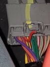
  • Performed 12v supply trace (and continuity) on contactor line on:
    • F93 (continuity pass)
    • X551, F29 (Continuity pass)
    • X535, Pin 2 and Pin 4 (12v Pass)
    • X950, Pin 6 (12v Pass)
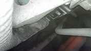
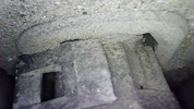
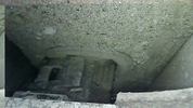
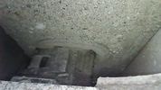
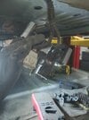
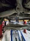
    • Dropped the battery pack: X036, Pin 5 (12v Pass)
    • Dropped the Battery pack: X035, Pin 5 (12v Pass)
  • Performed 12 supply trace (and continuity) on BMS line
    • Continuity on F53
    • X950, Pin 7 (12v Pass)
    • Dropped the battery pack: X036, Pin 2 (12v Pass)
    • Dropped the Battery pack: X035, Pin 2 (12v Pass)
  • Performed Ground Check:
    • Dropped the Battery pack: X035, Pin 12 & 8 (Continuity Pass)
    • Dropped the Battery pack: X036, Pin 12 & 8 (Continuity Pass)

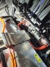
On March 31, 2024, the battery pack was dropped for further inspection of X036 and X035 to the pack. All inspections of the LV Rapid Mate connectors passed with respect to the contactor line. Battery pack was re-installed back into the vehicle. Unfortunately, due to time constraints from the shop, the battery pack was rushed and installed (missing one screw) and the LV Rapid Mate connector was NOT seated properly when re-installed. As a result, now there are a number of additional errors that show on the dash. Please refer to the initial error log above when looking at the logs for the actual issue, the additional errors that are now present indicate there is no communication to the pack at all since the rapid mate connector is not properly seated (except for showing the battery range left on the dashboard, 250km left).
 
  • Like
Reactions: Gtech
Upvote 0
So Tesla use UDS over CAN BUS to handle ECU diagnostics.
Tesla have multiple buses which can be accessed from the diagnostic connector under the middle screen. For this we want CAN BUS 3 (the drivetrain CAN) at a speed of 500kbps

You can use any cheap CAN BUS analyser to send and read these messages.

They have a login procedure for UDS which is the same seed and key for all cars luckily.

Below is an example of the CAN frames required to clear the BMS stress on a Model S, I've included a comment to show what is going on too...

DirectionCan IDDataComment
you send to car0x60202 10 03 00 00 00 00 00Tell the car to start diag session, note the 10 value for UDS Session Start
car responds with0x61202 50 03 AA AA AA AA AAResponse contains 50 (10 + 40)
you send to car0x60202 27 05 00 00 00 00 00start a secured session, note value 27
car responds with0x61210 12 67 05 00 01 02 03all good, note 67 (27 + 40). Start of seed
you send to car0x60230 00 00 00 00 00 00 00flow control message, meaning ok ready for more data
car responds with 2 frames, 1st0x61221 04 05 06 07 08 09 0Amore of the seed
2nd frame from car0x61222 0B 0C 0D 0E 0F AA AAfinal part of seed
you send to car0x60210 12 27 06 35 34 37 36thanks for seed, here is the key
car responds with0x61230 00 00 AA AA AA AA AAflow control, car is ready for more data
you send to car0x60221 31 30 33 32 3D 3C 3Ffirst part of key
you send to car0x60222 3E 39 38 3B 3A 00 00second part of key
car responds with0x61202 67 06 AA AA AA AA AAAll good, note the 67 (27 + 40), logged in basically
you finally send0x60204 31 01 04 06 00 00 00the thing you actually want to do, 06 means reset contactor stress.
car responds with0x61205 71 01 04 06 01 AA AACar completed the task, note the 71 (31 + 40) and the 01 confirmed completed.

So that is one example of a BMS stress reset, below are the others that I know (just replace the final send with these)...

Clear stress04 31 01 04 06 00 00 00
Reset WOT04 31 01 04 07 00 00 00
f16304 31 01 04 02 00 00 00
f15304 31 01 04 05 00 00 00
f15204 31 01 04 04 00 00 00
Open Positive Contactor Reset04 31 01 04 02 00 00 00
f02604 31 01 04 0A 00 00 00
w02604 31 01 04 01 00 00 00
? w02304 31 01 04 02 00 00 00

If anyone knows anymore then please add to this list to help the community out.

Hopefully this helps people out without the need to spend thousands on diag equipment.
Just for clarification, these x7 can frames must be sent in a row, or a specific timing must be respected ?
Thanks
 
Upvote 0