Welcome to Tesla Motors Club
Discuss Tesla's Model S, Model 3, Model X, Model Y, Cybertruck, Roadster and More.
Register

Model S - HPWC (High Power Wall Connector)

This site may earn commission on affiliate links.
Yes, I am served by a small rural co-op. They don't currently have the capability to offer me TOU service. My utility has an existing off-peak electric water-heater program that's similar ... so I think they are adapting that program for this purpose. My panel is located on interior of garage wall. Utility is telling me that I would pay an electrician to install a sub-meter provided by the utility on the exterior-side of the same garage wall where the panel is installed. The sub-meter is radio controlled, and would literally shut off the power to the HPWC (similar to how they shut off power to water heater). So HPWC would go dark at 7am and cycle back on at 11pm. When I installed my HPWC about a year ago, I also had the electrician install a NEMA 14-50 in addition, so I'd have a back-up if HPWC failed. So I think I could hook up either the HPWC or the NEMA 14-50 to the sub-meter ... That would allow me to use one for 11pm-7am most of the time, but could use the other if I needed a charge between 7am-11pm. Just wondering if it is a bad idea to hook up HWPC and subject it to this specific cycling or if it otherwise would be bad for the car/battery. Thanks for your comments ...
Thanks for the clarification on the local Utility plan ... your HPWC is fine with the power shut off on a daily basis :cool:
 
Okay, thank you. Will verify savings. Thanks for checking whether HPWC handle will disconnect when power is out. The local Tesla shop thought HPWC would be okay cycling on/off, but I will check with mother ship. The rate difference is $.12 vs $.0495. Yes, my car has the charger upgrade so HPWC is on 90 amp circuit breaker and pulls 72 amps. NEMA 14-50 is on 50 amp breaker and pulls 40 amps. Will consider putting sub-meter on NEMA 14-50 instead of HPWC ... My sense though is that this kind of off-peak plan is rare so that's why I wanted to ask. Thanks again.
 
Okay, thank you. Will verify savings. Thanks for checking whether HPWC handle will disconnect when power is out. The local Tesla shop thought HPWC would be okay cycling on/off, but I will check with mother ship. The rate difference is $.12 vs $.0495. Yes, my car has the charger upgrade so HPWC is on 90 amp circuit breaker and pulls 72 amps. NEMA 14-50 is on 50 amp breaker and pulls 40 amps. Will consider putting sub-meter on NEMA 14-50 instead of HPWC ... My sense though is that this kind of off-peak plan is rare so that's why I wanted to ask. Thanks again.
Yes, your plan is really strange. I've never heard of a plan that cuts the power.

I have a different strange plan. Mine is a pilot program. $30/mo for unlimited off peak charging on a 50A or smaller breaker OR $50/mo if greater than 50A. Any charging during peak time just goes against the standard electrical rate. If I exceed 10% on peak time, all of it reverts to standard rates. I went with the $30/mo so I have an HPWC on a 50a breaker. Still meets my needs just fine!

I've done the math and I'm basically paying $0.05 per kWh vs $0.12.

It was about $200 more to have the meter can installed on the circuit.
That sounds like a great plan. Did you have to get a second meter installed for the 50 amp circuit?
 
Does anyone have the EU model of the HPWC and has photos of the control board EVWTSHT-1 ?
I've procured a "broken" charger where the control connector CNA5 had been ripped off. I can replace the connector, but some of the circuit board tracks have been damaged and can't quite work out where they are meant to go.
 
Sorry this is long....

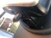
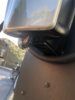
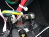
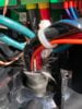
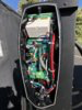
Some questions about the HPWC wiring and it's cable. I'm about to do a repair on three chargers we have installed at a commercial location. People kept pulling the charge cables out to full length and now the cables are slowly pulling out of the bottom of the units. I killed the power to one at the breaker, took the HPWC apart and re-wedged the rubber outer cover back inside the unit, and cranked down the holder again to hold it in place. (see pics). In the 3rd pic you can see the holder for the hose that is missing the hose. The wires themselves seem ok on the first one I serviced, just the rubber outer casing was pulled down. The other two are a little more worn...

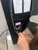
Does anyone have a description of the cables inside the charge cable? On one of the HPWC I haven't worked on yet it appears that one of the smaller cables has either ripped out or wasn't connected to anything in the first place. (really small, like a single cable inside ethernet cable small). The charger itself still seems to work fine even though that one cable is not connected. I don't have a pic of the ripped out cable handy but I will try and get one next time I am over there finishing the repair. What my plan was to solve the rip out problem was to get a short length of PVC pipe, cut it in half lengthwise, and use hose clamps to hold the cable down against the pedestal under the 1/2 PVC pipe so it wouldn't crimp the cable. That way the strain would be at the PVC part and not where the charge cable goes into the HPWC unit, preventing it from pulling out.

The other thing I noticed: At this location there are three HPWC on what I thought was a single 100amp circuit but with com cable between them to share the load. I know each charger is capable of outputting 80amps individually, I've tested each one on their own. Also they output less when two or more cars are plugged into them at the same time, acting exactly as you would expect for a load-sharing setup.

When I went to kill the power to the chargers for my initial repair, I noticed that the sub-panel feeding the three chargers actually has three 100amp circuit breakers installed, and you can manually kill the power to each HPWC individually. This as opposed to the normal load sharing setup where a sub-panel's single 100amp circuit feeds a single junction box that in turn feeds 2-4 chargers depending on your setup.
When it was initially installed I know the electrician said they pulled a much beefier cable then was needed from the main panel to the sub panel both because of distance (sub panel is probably 100-150' away from the main panel) and because they wanted some extra overhead in the event they might want to add a additional 40amp J1772 charger later. I had thought they pulled whatever was needed for 150 total amps, but it looks like they pulled enough for 300amps? Tomorrow I'll try and get a peek at the main circuit breaker that feeds to the sub-panel, that should clear up just how much juice is going to the sub-panel.

If there is 300amps going to the sub-panel, could I just unhook the control wire and change the settings on each HPWC to go at 80amps each instead of load sharing the 100 amps? It appears that while the HPWC are set up properly to load share, they don't need to as each charger might have the proper 100amp feed going to it.

My final question is one pedestal has two chargers on it, the other just has one. The one with 2 chargers on it is fed from a single conduit (The wiring for each HPWC shares the conduit), the pedestal that only has one HPWC is fed by its own separate conduit. The chargers are anywhere from 5-15' from the sub-panel. The wire to each HPWC is clearly rated to handle 80amps as when one car is plugged in it pulls that just fine. If it turns out that I have 300amps overhead at the sub-panel level, and each HPWC could in theory just work as stand alone 80 amp chargers, is there any issue having two of them feeding 80amps each through the same conduit (but separate wiring)? Or should if anything the one HPWC on it's own just be converted to 80amp solo and the two sharing a pedestal become a load sharing 80amp total. (up to 80 when single use, 40 each when both are in use) to minimize heat from the cabling.) I'd just have to see which HPWC is set as the master.


Hopefully this makes sense.
 

Attachments

  • IMG_2243.JPG
    IMG_2243.JPG
    237.1 KB · Views: 139
  • IMG_6339.JPG
    IMG_6339.JPG
    200.6 KB · Views: 113
  • IMG_1423.JPG
    IMG_1423.JPG
    370.6 KB · Views: 100
  • IMG_9455.JPG
    IMG_9455.JPG
    352 KB · Views: 104
If you truly have 300 amps feeding the subpanel with the 3 100 amp breakers, all you need to do to make them independent is change the rotary switch on the two slaves from the Slave setting to the proper 100 amp setting. That will make them independent, even if the comm cable is there. However, I doubt you have a 300 amp sub-panel feed. If it is 150 amps, there is no better way to set them up. Well, maybe one alternative would be two sharing 90 amps (72 amps to the car) and one fixed at 60 amps (48 amps to the car). You would have to change all the breakers for that reconfiguration.
 
If you truly have 300 amps feeding the subpanel with the 3 100 amp breakers, all you need to do to make them independent is change the rotary switch on the two slaves from the Slave setting to the proper 100 amp setting. That will make them independent, even if the comm cable is there. However, I doubt you have a 300 amp sub-panel feed. If it is 150 amps, there is no better way to set them up. Well, maybe one alternative would be two sharing 90 amps (72 amps to the car) and one fixed at 60 amps (48 amps to the car). You would have to change all the breakers for that reconfiguration.
It's not clear to me why he would need to change the breakers. The breakers are there to protect the wiring and since the wiring is sized to 100amps, changing the settings on the HPWCs so that they top out at a lower amperage wouldn't change that. However, I agree that the subpanel or even the main panel is probably the limiting factor. It could also have nothing to do with the supply and be a strategy to avoid demand charges. I wouldn't change the settings without consulting an electrician and/or whoever decided to configure them that way.

Actually, I wouldn't change them at all since that seems like a pretty sweet setup as it is.
 
It's not clear to me why he would need to change the breakers. The breakers are there to protect the wiring and since the wiring is sized to 100amps, changing the settings on the HPWCs so that they top out at a lower amperage wouldn't change that.
I think that is because he found that a small communication wire was broken, so isn't confident that the load sharing is really working properly.
 
I think that is because he found that a small communication wire was broken, so isn't confident that the load sharing is really working properly.
My understanding is that if the communications wire were broken, the affected slaves wouldn't work at all. Nor should users have access to pull on them. The wire he's referring to seems to be in the cable that goes to the car. I didn't chime on that because I don't know the color coding in there. However, a small wire in that cable would either be:

  • The pilot, without which the car wouldn't charge (+-12v)
  • The low voltage power that powers the signal to open the charge door when the button is pressed. (3.3v?)
  • The proximity wire, which may not be there and probably isn't used at that end and may not be connected. (12v)

They are all three low voltage (<12v) and a simple repair should work fine.
 
Once I finally got access to see the primary circuit breaker panel it all became moot as the sub-panel is only fed by 2/0 AL wire and a 125 amp breaker. Given the distance of the run, they needed 2/0 to prevent voltage drop, but it doesn't leave much headroom for additional power out at the sub-panel. Even adding a 30 or 40amp J1772 charger out there would mean dropping the max the HPWC can output. So basically no changes to the way the HPWC are set up, they work fine.

Now the other question I had about the charge cables themselves is still floating out there. As mentioned before, the load sharing communication was working just fine, exactly as it was supposed to be. 1st car to plug in gets up to 80 amps regardless of the charger used. 2nd car plugs in and it drops the charge to 40 amps to each car, and if a third car joins it's cut again to ~26 amps to each car.

Back to repairing the units themselves. Obviously be sure you have killed the power to the HPWC at the breaker.
Check under your HPWC, you don't want the charge cable to be pulling out of the bottom of the unit.
IMG_2243.JPG

IMG_2065.JPG
You gently undo the silver bracket at the bottom that's supposed to hold the cable in place, pull it out of the way. Then gently work the whole cable back up inside the bottom of the unit, re-sealing the rubber boot around the cable and the bottom of the HPWC. This is by far the worst part, a royal pain in the ass. After getting it re-sealed you need to also re-attach the silver bracket to hold the cable as it was supposed to be held in the first place.

IMG_7078.JPGIMG_4532.JPGIMG_7178.JPG
All the while being careful with the four super fragile little connections on the right side that also go into the charge cable.
IMG_4706.JPG
So the picture below shows the white cable that isn't connected to anything on all three HPWC. Originally I thought it was just one charger had some damage, but on further inspection, this white cable isn't connected to anything on all 3. The chargers all work fine without this cable connected. I was just wondering what it was.
IMG_4530.JPG

IMG_4531.JPG
Finally to reduce the odds of the cords pulling out again I'm going to create a little stress reduction cable holder with some PVC pipe cut in half and hose clamps to prevent them from pulling out again. (Pics for that will come later)


Anyone know what the little white cable is inside the charge cable?
 

Attachments

  • IMG_9064 2.JPG
    IMG_9064 2.JPG
    349.1 KB · Views: 95
  • image.png
    image.png
    15.6 KB · Views: 95
My understanding is that if the communications wire were broken, the affected slaves wouldn't work at all. Nor should users have access to pull on them. The wire he's referring to seems to be in the cable that goes to the car. I didn't chime on that because I don't know the color coding in there. However, a small wire in that cable would either be:
Right, in the charging cable, but one of those is still using communication related to the load sharing. Remember that in the descriptions of how the load sharing logic works it does not just divide the total amount of current evenly among however many cars are connected. It says that it will prioritize more amps to the car(s) that have lower states of charge early on. So there is some communication from the car back into the wall connector of its charge state to let it know how to adjust the amp levels. So yes, a broken wire in the charge cable could still cause the load sharing to not work quite right. I have no idea if it would have some kind of default operation if that wire were broken, though.
 
...
Anyone know what the little white cable is inside the charge cable?

I'm pretty sure that's the proximity wire, which has no function at this end of the cable. It is pulled up by the car, and resisters in the handle pull it down to signal that the plug is connected and separately when the button is pressed. The car is required to stop drawing current in milliseconds when the button is pressed to avoid arcing when the plug is removed. For some reason, every J1772 cable I've seen seems to have a wire dedicated to it, although it's not used.
 
Last edited:
  • Informative
Reactions: Fiver
Remember that in the descriptions of how the load sharing logic works it does not just divide the total amount of current evenly among however many cars are connected. It says that it will prioritize more amps to the car(s) that have lower states of charge early on. So there is some communication from the car back into the wall connector of its charge state to let it know how to adjust the amp levels. So yes, a broken wire in the charge cable could still cause the load sharing to not work quite right. I have no idea if it would have some kind of default operation if that wire were broken, though.


This part I'm unsure about. In my experience using these three connected chargers (and now seeing inside all three) I don't think the load sharing is quite as smart as people think.

The three chargers I just worked on all are capable of 80 amp charging. Once inside for the repair I noted one is set as 80amps, ("D" on the jumper) and the other 2 are set to "F" or slave. The one set to "D" only has communication wire out the "out" side. The middle HPWC has comm wire coming both in and out (set to "F") and the final unit just has comm wire on the in side, (also dip switch set to "F").

Anyway, 1 car gets up to 80 amps, if a second car plugs in you get 40 each, and a 3rd drops the charge on all three down to ~26. If one car tops off and stops charging, the other 2 don't immediately bump up to 40amps each, they stay at ~26. After a few minutes they both might raise up a few amps each, but never really split the newly freed up power they should have available. This action also seems hit or miss. Usually there's only 2 cars plugged in at this location. I've noticed that my car (with dual chargers) will slowly raise up the charge rate once the other car appears to be topped off, but I've never seen my amps go above 50 while the other car remains plugged in (but done charging). And the slow amp raise takes awhile, it's not instant. Also I've never ever seen any sort of "priority" given to any one car based on SoC.

Also the setup I was working on was a little odd as usually there is one 100amp (or whatever) breaker that feeds a Jct box that in turn feeds the 3 (in my case) chargers. That way the max load is only 80 amps, and the comm cable keeps all the chargers in line and prevents them from puling more then 80 amps total as a group.

The setup where I just was working had all three fed by their own 100amp breakers, each wired independently. So if the communication cable is disconnected, and the dip switch settings changed, they could pull 80amps each, which on a 125amp (total) sub-panel could be bad. Thankfully they are set so one is master and if the cable becomes disconnected or whatever the slaves will just stop working. When the dip switch's are set to slave, they won't work unless they get communication from the "master" unit.
 
Also I've never ever seen any sort of "priority" given to any one car based on SoC.
I didn't make it up. When these first came out in summer 2016, people were testing and investigating them. See this post from @sowbug, where he tried it with two vehicles at different states of charge, and the wall connectors do show an offset of how many amps they will allocate to each car based on that. He was seeing 26-30A for the more full car and 48-51A for the less full car. But that was in summer of 2016, when it first came out. Maybe they did simplify the operation of them since then for some reason.
New Wall Connector :)

Also the setup I was working on was a little odd as usually there is one 100amp (or whatever) breaker that feeds a Jct box that in turn feeds the 3 (in my case) chargers. That way the max load is only 80 amps, and the comm cable keeps all the chargers in line and prevents them from puling more then 80 amps total as a group.

The setup where I just was working had all three fed by their own 100amp breakers, each wired independently. So if the communication cable is disconnected, and the dip switch settings changed, they could pull 80amps each, which on a 125amp (total) sub-panel could be bad.
A junction box with direct ties or a subpanel with separate breakers are both valid ways to do this and serve the same kind of function for these load sharing systems. They are still both fed by one main line back to the main panel. See this post for explanation:
What's up with HPWC?
 
@Fiver thanks for all the detail on how the load sharing behaves!

The setup where I just was working had all three fed by their own 100amp breakers, each wired independently. So if the communication cable is disconnected, and the dip switch settings changed, they could pull 80amps each, which on a 125amp (total) sub-panel could be bad. Thankfully they are set so one is master and if the cable

It is really no different than an HPWC on a 50a breaker (or pick any size). If the rotary switch is changed, it may pull more. Is the sub panel protected upstream with an appropriate sized breaker?
 
I didn't make it up. When these first came out in summer 2016, people were testing and investigating them.

Yea I remember reading about that as well. All I can report is in my case I have not seen any sort of priority given to any car regardless of the SoC when plugged in. The other 80 amp 3 HPWC shared setup I've used is at Snowbird, Utah. When had the "opening" party we plugged in three cars and each pulled ~26 amps regardless of SoC as well. When the car doing test rides for people left the two remaining cars popped up to 40amps each instantly. Again, no priority seemed to be given. Then again, both our cars were at roughly equal SoC at the time.

@Fiver Is the sub panel protected upstream with an appropriate sized breaker?

As others have mentioned, the setup is wired correctly. The sub-panel is fed by a 125amp breaker and 2/0 AL wire.

If someone messed with the settings inside the HPWC, one could go at a full 80amps, and a second might be OK up to 40 amps but that would be cutting it close (It would technically be a 150amp load de-rated 20% to 120amps on a 125amp breaker). If a third car plugged in it would pop for sure though.
 
  • Informative
Reactions: brkaus