Welcome to Tesla Motors Club
Discuss Tesla's Model S, Model 3, Model X, Model Y, Cybertruck, Roadster and More.
Register

NEMA 14-50 Plug Meltdown / Near Fire

This site may earn commission on affiliate links.
Just wanted to give thanks to this thread. I installed a 14-50 circuit on my own and used a leviton receptacle with the screw clamps. I opened up the box after reading this thread, and with the exception of the ground wire, all the screws were pretty loose. More than 1 full turn to get them tight again. It's been 15 months since install. I did notice that my voltage was lower than when it was first installed. The app and car used to read over 240V. Lately it was around 236V. Now that the screws are tightened, it's back up to 241V.

I'll check it periodically now to make sure things are still tight. And may consider replacing the receptacle at some point.
 
I noticed that the voltage displayed on the screen of my SR+ while charging from a 14-50 outlet at home is around 232 to 234V. Is that too low?

After reading this thread I'm thinking the safest option is just to install a Tesla wall charger. Can I have an electrician "convert" the newly installed 14-50 (with 50 amp breaker) to a wall charger setup?
 
  • Informative
Reactions: Jaywlker
I noticed that the voltage displayed on the screen of my SR+ while charging from a 14-50 outlet at home is around 232 to 234V. Is that too low?

After reading this thread I'm thinking the safest option is just to install a Tesla wall charger. Can I have an electrician "convert" the newly installed 14-50 (with 50 amp breaker) to a wall charger setup?

What is the voltage the moment you plug in the car and before it ramps its charge rate? If it starts out right about at the same spot as where it ends up then I would not be worried. Your utility might just deliver a little bit low voltage (they commit to a certain tolerance, usually about 5%, though sometimes they allow a wider tolerance).

But yes, you could likely easily re-use the existing wiring to hard wire a Wall Connector.

Please note that you are seeing a small self selected sample set here in this thread. There are 10's of thousands of folks that charge off 14-50 receptacles perfectly successfully for years, so I would not freak out too much. ;-)
 
I noticed that the voltage displayed on the screen of my SR+ while charging from a 14-50 outlet at home is around 232 to 234V. Is that too low?

After reading this thread I'm thinking the safest option is just to install a Tesla wall charger. Can I have an electrician "convert" the newly installed 14-50 (with 50 amp breaker) to a wall charger setup?
That’s only a 3% voltage drop from 240V so it’s normal. Sure you could have a Wall Connector hardwired instead but you’d have the same voltage drop under load. I’d stick with what you have.
 
It's great that no major damage occurred.

Your melted connector most likely was caused by a loose connection to one of the terminals. A loose connection increases the resistance in the circuit. Power equals: current squared times resistance--more resistance, more power, ie. more heat. There may have also been some arcing or sparkes which can result in a fire. As most posters here stated, buy the best quality outlet you can (USA made if possible) and make sure all the connections are tight. I re-purposed a 53 year old NEMA 10-30 electric dryer outlet with a bakelite housing. No problems after one year of use.
 
  • Informative
Reactions: Jaywlker
I'd ask electrician or inspector to verify installation under load with FLIR camera or equivalent . See Got a Flir camera to check for electrical safety - Pictures! for examples.
As far a a Flir camera, the receptacle body seems where the heat was being generated via the loose black screw, that would’ve been blocked by the plug adapter from being uncovered by the Flir. Any laser style temp gauge can detect heat being generated in a loose connection, though Flir is more “sexy”, but commensurately much more expensive. $100 versus $400+
You can also view the charging current and voltage at which that current is operating at in the phone app. Pay attention, as that is indicating the “Voltage drop”, it increases as the load increases. 5% should be the total voltage drop allowed, the only way to lower voltage drop is:, shorten the length of the run, or distance from the panel, lower the current, which increases charging times, or increase the size of the feeder conductor.
 
  • Informative
Reactions: Jaywlker
+1

It's up to the individual. If you don't feel comfortable... hire someone. If you want to learn and DIY... learn and DIY. There are plenty of resources available to ensure you do it correctly. Just do your homework. All this DIY-shaming is kinda silly.

This was also installed by a licensed electrician. They're not magic...

View attachment 417938
I’m looking at your wall charger and the failure of the conductor initially connected, it appears like there’s a fair amount of partially melted copper conductors outside of both the insulation and the lug it connects to. Can you determine if those melted “strands” were under the terminal or just melted and pulled away from the insulation? Any torque value mentioned in any accompanying literature of said charger for those lugs?
 
  • Informative
Reactions: Jaywlker
I’m looking at your wall charger and the failure of the conductor initially connected, it appears like there’s a fair amount of partially melted copper conductors outside of both the insulation and the lug it connects to. Can you determine if those melted “strands” were under the terminal or just melted and pulled away from the insulation? Any torque value mentioned in any accompanying literature of said charger for those lugs?

Not real sure... this happened over a year ago and has since been fixed. Not my work. A friend called me to take a look. His electrician blamed the equipment....

The wire in the picture was in the terminal but I pulled it back to show the damage.
 
  • Informative
Reactions: Jaywlker
I read this thread last night and contacted my electrician if he can avoid using leviton parts for my NEMA 14-50 outlet install later this month. He mentioned he can use vista parts instead.

My terrible Googling did not come back with any results regarding vista quality, does anyone know how vista electrical parts fare against leviton?
Try Hubble, industrial rated receptacle.
 
One question I would have, is was the connection wire aluminum (say AWG #6) or was it copper (say, AWG #8)? ***CORRECTION*** just looked at the pics and it looks like he used #6 Copper which should easily handle 40 amperes. Copper is much more tolerant than aluminum for loose connections and therefore I'd strongly suggest at least part of the problem was that horrible GEN 1 nema 14-50p adapter, since the connection pins on it heat UNACCEPTABLY on all of them at 40 amperes.

The problem with an Aluminum wire and Leviton combination is that Leviton's cheesey screw terminals in lieu of box lugs is that it is difficult to remain TIGHT. If I was forced to use such junk I'd retighten the connection after a few days to make sure the aluminum wire was tight in the connection - and of course as with all Aluminum Terminations to clean the wire (to get rid of Al-Oxlde film, a non-conductor), with emery cloth, and then put some kind of no-ox (Oxy-Ban, etc.) on the connection to keep the air and water out.

The old 40 amp original Tesla convenience cord had multiple problems - 40 amperes through the Nema 14-50P adapter where the juice went through 2 microscopic connection points was just asking for trouble - as Tesla themselves realized by eventually doing the following:

1). Monitoring the 'droop' and decreasing the current by 80% in stages until the 'droop' was deemed acceptable. This was overly cautious in places with distant wiring or stingy utility policies, yet it did prevent fires due to droop at the poor connection Tesla adapter. I couldn't believe the heat coming out of one at a model S at the Mississauga (Toronto) Service Center, of all places.

1a). (The fact that the 'portable EVSE' itself only used a 30 ampere rated relay with 40 amperes going through it explains why many of the 'mini S-shaped' evse's melted and needed to be replaced).

2). Putting a 'fuse wire' in later adapters so that the juice will shut off prior to a fire.

3). Bringing out NEW 32 ampere (model 3 style) travelling cords that have the adapter some distance AWAY from the wall outlet... The lower current and less heat at the wall outlet has just got to make things much safer.
I’d never suggest the use aluminum conductors for charging circuits just for the expansive characteristics of the aluminum...Copper only.
 
  • Like
Reactions: Jaywlker
I believe it’s actually for protection of the conductors, not the breaker...

This would intuitively be true, but actually it is not. The conductor is rated to the full ampacity stated in the charts regardless of duty cycle (continuous load or not). The 80% derate is all about the uncertainty as to where the breaker will break. They don’t want it breaking over the rated current as the wire is only rated up to the breaker rating generally.

The proof to this is that you can get 100% rated breakers. Generally I think they are larger commercial microprocessor controlled ones and so they are a lot more accurate. This lets you get 100% out of your wire.
 
Tesla supposedly has advanced algorithms that continuously monitor for voltage drops during the charge cycle. Somehow these algorithms must have failed in order for the outlet to be smoking. The only thing that saved you was the circuit breaker.
 
Tesla supposedly has advanced algorithms that continuously monitor for voltage drops during the charge cycle. Somehow these algorithms must have failed in order for the outlet to be smoking. The only thing that saved you was the circuit breaker.

If that's true it sucks at it's own algorithm. My circuit breaker melted down before it tripped because of a chattering contact inside the breaker. The Tesla just kept pulling until it melted completely.

This would intuitively be true, but actually it is not. The conductor is rated to the full ampacity stated in the charts regardless of duty cycle (continuous load or not). The 80% derate is all about the uncertainty as to where the breaker will break. They don’t want it breaking over the rated current as the wire is only rated up to the breaker rating generally.

The proof to this is that you can get 100% rated breakers. Generally I think they are larger commercial microprocessor controlled ones and so they are a lot more accurate. This lets you get 100% out of your wire.

100% agree...I test breakers at work to ensure they still trip so I will put them under a 120% load until they trip. Sometimes they don't trip until I hit 140%+ for 5 minutes or so. Temperature has a lot to do with it. If it's cold where the breaker is, but the wires are wrapped in insulation, it's possible that the wire could fail before the breaker trips.

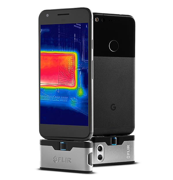
A cheapish FLIR is a good thing for a homeowner to have. $200 for your smartphone. Probably cheaper elsewhere.

flirone-gen3-consumer.png


FLIR ONE Gen 3 Thermal Camera for Smart Phones | FLIR Systems
 
This would intuitively be true, but actually it is not. The conductor is rated to the full ampacity stated in the charts regardless of duty cycle (continuous load or not). The 80% derate is all about the uncertainty as to where the breaker will break. They don’t want it breaking over the rated current as the wire is only rated up to the breaker rating generally.

The proof to this is that you can get 100% rated breakers. Generally I think they are larger commercial microprocessor controlled ones and so they are a lot more accurate. This lets you get 100% out of your wire.
Actually then why would different conduit types dictate more allowable numbers of similar sized conductors, ie non flexible metallic conduit versus imc? There’s a metric on the amount of heat each of these different conduits allow each of the conductors to pass off, without damage. A conductor is protected at its source primarily by a circuit breaker or ocpd. Derating the amperage permitted by continuous load has nothing to do with the heat the breaker will open at... The 100% breaker you may be thinking of is called a “HACR” rated c/ b. imho
 
Actually then why would different conduit types dictate more allowable numbers of similar sized conductors, ie non flexible metallic conduit versus imc? There’s a metric on the amount of heat each of these different conduits allow each of the conductors to pass off, without damage. A conductor is protected at its source primarily by a circuit breaker or ocpd. Derating the amperage permitted by continuous load has nothing to do with the heat the breaker will open at... The 100% breaker you may be thinking of is called a “HACR” rated c/ b. imho

The number of conductors allowed in a conduit is controlled by wire fill calculations. Different conduit types/sizes have different internal areas. There is no assignment for different types of heat dissipation for different conduit types (EMT, IMC, PVC, etc...). There are rules for the number of current carrying conductors you can have in a conduit before you have to derate the capacity of each wire in the conduit, but those are the same for the various conduit types.

Then each wire type has insulation ratings, that dictate how hot they can get without melting and so you use the corresponding table values depending on that rating.

As far as breakers go: Yes, the breaker is what protects the wire. The key is that a regular household breaker will break somewhere in the 80-100% range of its rating (in theory) when under a continuous load. So the wire needs to be rated to that 100% of the breaker rating, but you can't trust it not to break at 80%, so if the wire and breaker is rated at 50a, then you can't put an expected continuous load on that circuit over 40 amps since you don't know where in between 40 and 50 amps the breaker will actually trip when loaded for hours on end.

The HACR rating does not have anything to do with 100% rated breakers. HACR rated simply means that the "trip curve" for the breaker somewhat approximates that of a fuse. It is all about making sure the breaker won't nuisance trip when a big surge load (i.e. electric motor) kicks on. It does not have anything to do with continuous load ratings.
 
  • Informative
Reactions: Jaywlker
@eprosenx, why is it that open air conductors are rated to carry more current? Why do you have to derate current capacity for more than three current carrying conductors per conduit of any material? Heat is why...
PS, a household breaker uses bi-metal contacts, that when heated enough open, again heat. An item you can purchase at Hd for $3.50 doesn’t have too many smarts built in, simple, tested, and must work or we’d see more houses burning down.
That’s also with said homeowners interpretation of the NEC, whom they’re then getting fine points from the guys working the isles at Hd...not to disparage any workers, but they aren’t electrical professionals. As you and I are arguing these points many never spend a second considering...
 
  • Like
Reactions: Jaywlker
As far as breakers go: Yes, the breaker is what protects the wire. The key is that a regular household breaker will break somewhere in the 80-100% range of its rating (in theory) when under a continuous load. So the wire needs to be rated to that 100% of the breaker rating, but you can't trust it not to break at 80%, so if the wire and breaker is rated at 50a, then you can't put an expected continuous load on that circuit over 40 amps since you don't know where in between 40 and 50 amps the breaker will actually trip when loaded for hours on end.

@eprosenxAs you and I are arguing these points many never spend a second considering...

Good information on both sides of the argument!
 
  • Like
Reactions: Jaywlker